
Dry transformer heater

a transformer heater and transformer technology, applied in the direction of transformer/inductance with temperature compensation, basic electric elements, electrical equipment, etc., can solve the problems of condensation inside the transformer housing, dew-point temperature not exceeded, and disadvantageous dripping

Inactive Publication Date: 2015-10-27
ABB (SCHWEIZ) AG
View PDF9 Cites 2 Cited by
  • Summary
  • Abstract
  • Description
  • Claims
  • Application Information

AI Technical Summary

Benefits of technology

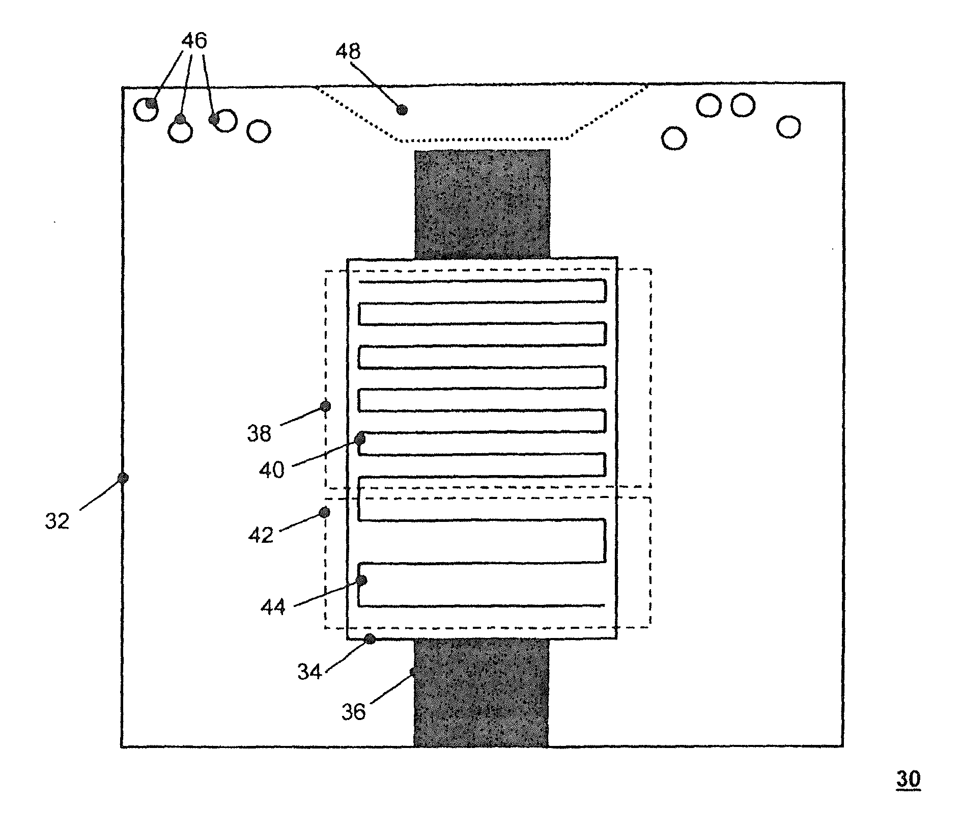
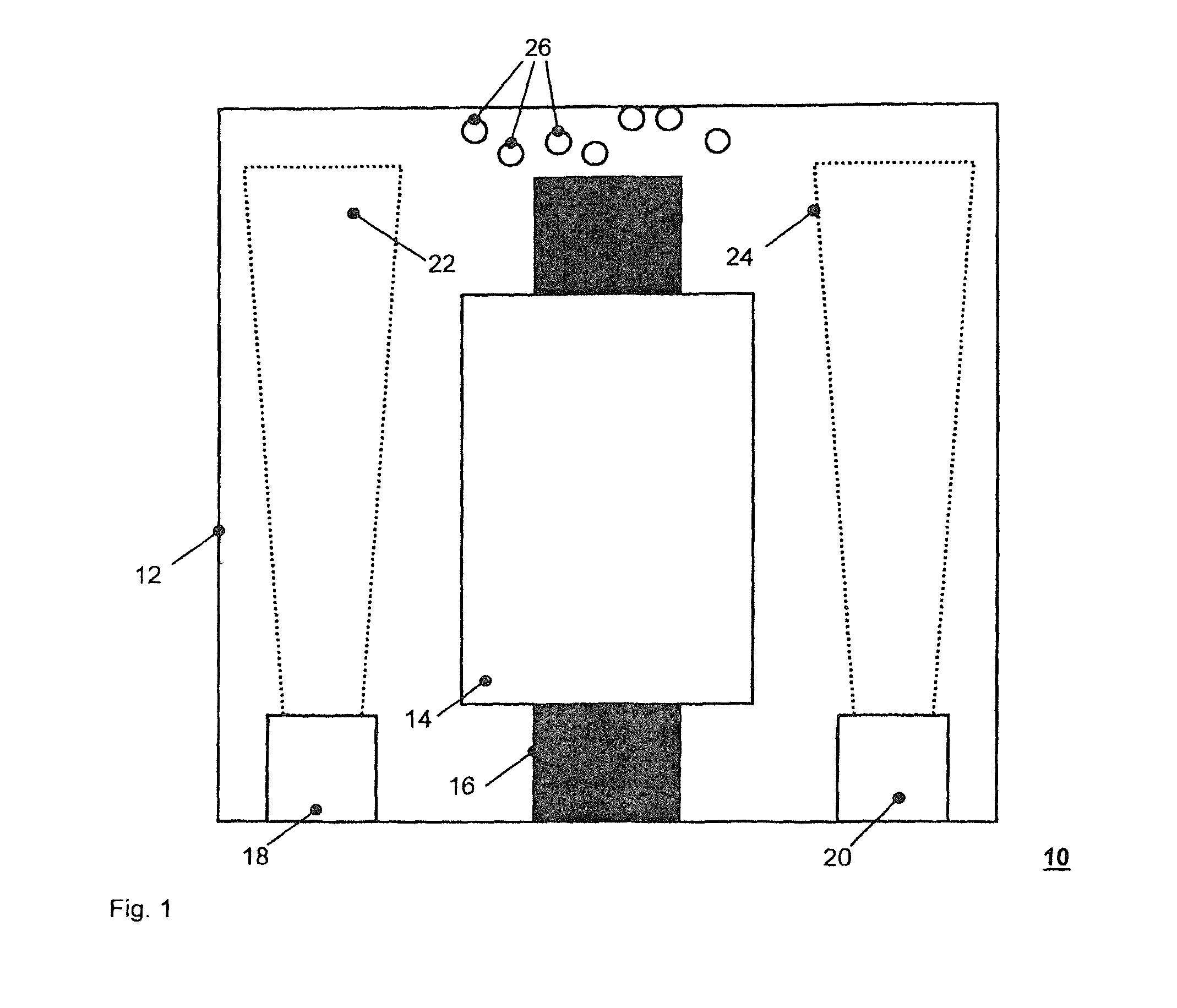
[0014]According to an exemplary embodiment of the dry-type transformer heater, the means for direct primary input of thermal power into the insulation layer can be controlled independently of the electrical operation of the transformer winding. For a start, this makes it possible to operate the dry-type transformer heater both as a pure space heater and as an additional heater during operation of the transformer. The transformer windings are lossy, with the result that thermal power arises in the transformer windings during operation of the transformer. Depending on the external temperature and the power loss which arises, this can already be sufficient to avoid condensation; however, depending on requirements, additional thermal power of the dry-type transformer heater can also be necessary. By means of the controllability according to the present disclosure, the means for direct primary input of thermal power can be controlled in a targeted manner such that a sufficiently high temperature above the dew point is ensured.

Problems solved by technology

For example, in the event that an encapsulated transformer is subjected to frequent shutdowns depending on use, condensation can form inside the transformer housing since the transformer then cools down owing to the lack of heating effect of the winding losses.
Even during permanent operation of an encapsulated transformer, condensation can be formed if the transformer is positioned in such a cold working environment that the winding losses do not lead to sufficient heating of the transformer or the housing thereof, with the result that the dew-point temperature is not exceeded.
However, the transformer windings and the housing region thereabove are not directly covered by the heating region and so condensation can form there which can drip in a disadvantageous manner, for example from the upper housing region, onto the transformer windings located below.

Method used


Image

  • Dry transformer heater
  • Dry transformer heater
  • Dry transformer heater

Examples


Embodiment Construction

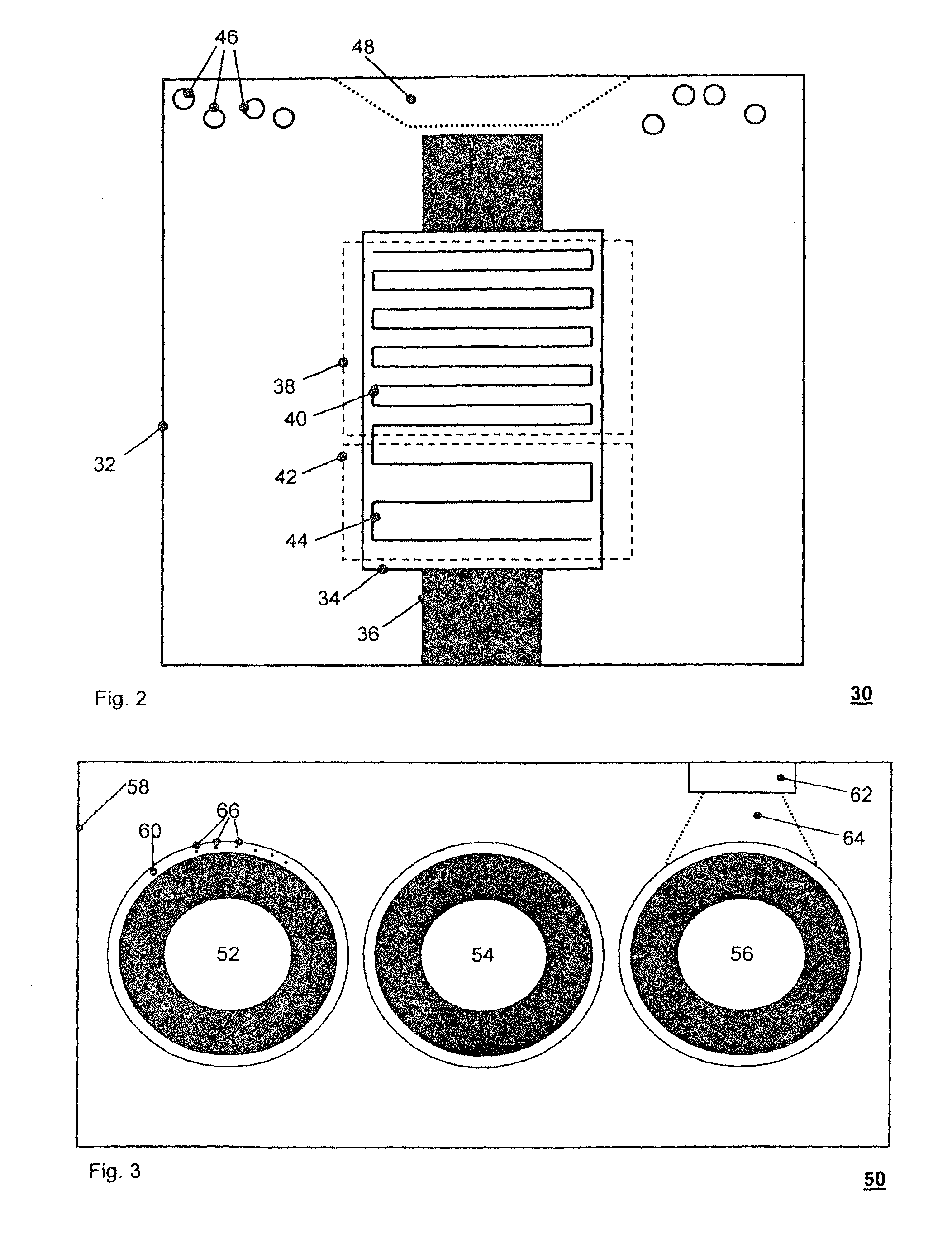
[0011]Exemplary embodiments of the present disclosure provide an improved dry-type transformer heater which avoids the drawbacks associated with known techniques as outlined above. According to an exemplary embodiment, the dry-type transformer heater of the present disclosure includes, in addition to the respective winding conductor, means for direct primary input of thermal power into the respective insulation layer.

[0012]The term “housing” in the scope of the present disclosure can mean both that the transformer winding is fixedly arranged in the housing and is movable therewith. However, it likewise means that a transformer winding or else the entire transformer is arranged in a closed room which does not directly form part of the transformer itself. This can be, for example, a closed room in the hull of a ship or else a room inside a building.

[0013]According to an exemplary embodiment of the present disclosure, by means of the direct primary input of thermal power into the insul...


PUM

PropertyMeasurementUnit
rated voltagesaaaaaaaaaa
thermal poweraaaaaaaaaa
temperatureaaaaaaaaaa

Abstract

A dry-type transformer heater includes a closed housing, and at least one transformer winding arranged in the housing. The at least one transformer winding includes at least one corresponding winding conductor and a corresponding insulation layer surrounding the transformer winding, respectively. In addition to the respective winding conductor, at least one coil heating wire is provided in at least one of the insulation layer and on the surface of the insulation layer to input thermal power into the respective insulation layer.

Description

RELATED APPLICATIONS[0001]This application claims priority as a continuation application under 35 U.S.C. §120 to PCT / EP2012 / 001088, which was filed as an International Application on Mar. 10, 2012 designating the U.S., and which claims priority to European Application 11003004.6 filed in Europe on Apr. 11, 2011. The entire contents of these applications are hereby incorporated by reference in their entireties.FIELD[0002]The present disclosure relates to a dry-type transformer heater.BACKGROUND INFORMATION[0003]It is generally known that dry-type transformers are used in power distribution systems to adapt the voltage levels of different system components. These have a power range of, for example, 100 kVA to some 10 MVA and are provided for rated voltages between, for example, a few kV to 110 kV. In contrast to oil-filled transformers, a liquid insulation medium is dispensed with here; rather, for example, the windings are surrounded by a solid insulation material, such as a fiber ro...

Claims


Application Information

Patent Timeline
Patent Type & Authority Patents(United States)
IPC IPC(8): H01F27/08H01F27/02H01F27/10H01F27/00H01F27/40
CPCH01F27/008H01F27/402
Inventor BOCKHOLT, MARCOSCORNELIUS, FRANKTEPPER, JENSESENLIK, BURAKPATEL, BHAVESCHWEBER, BENJAMIN
Owner ABB (SCHWEIZ) AG
Learn More