Control of a laser inertial confinement fusion-fission power plant
a fusion-fission power plant and inertial confinement technology, applied in the direction of nuclear reactors, nuclear elements, greenhouse gas reduction, etc., can solve the problems of fusion-fission engines that did not advance beyond the conceptual stage, and its long-term sustainability is difficult,
- Summary
- Abstract
- Description
- Claims
- Application Information
AI Technical Summary
Benefits of technology
Problems solved by technology
Method used
Image

Examples
Embodiment Construction
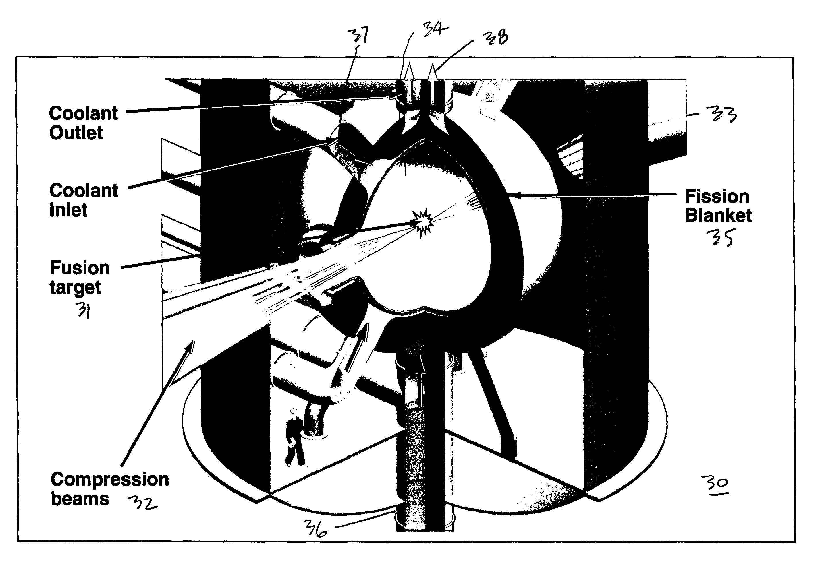
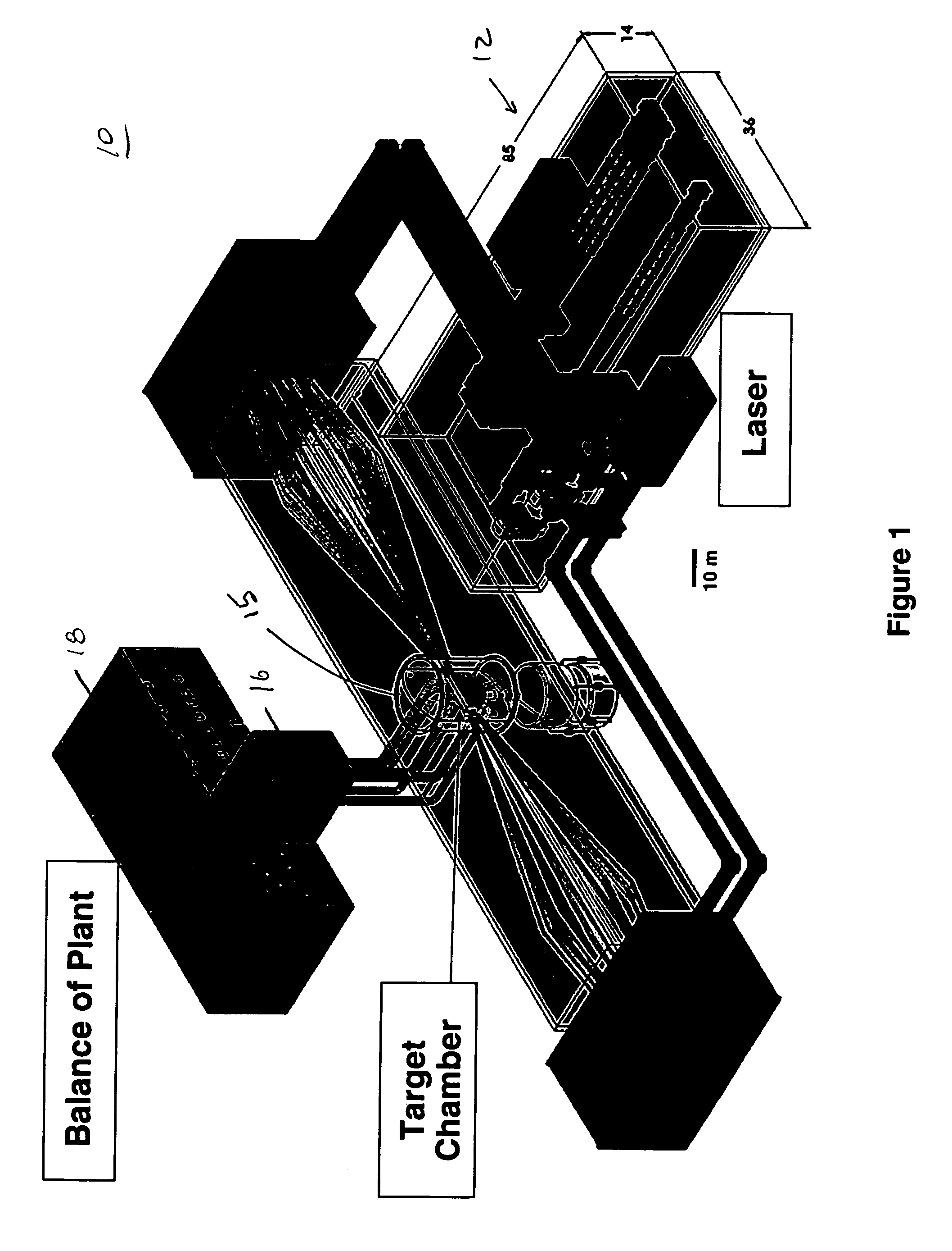
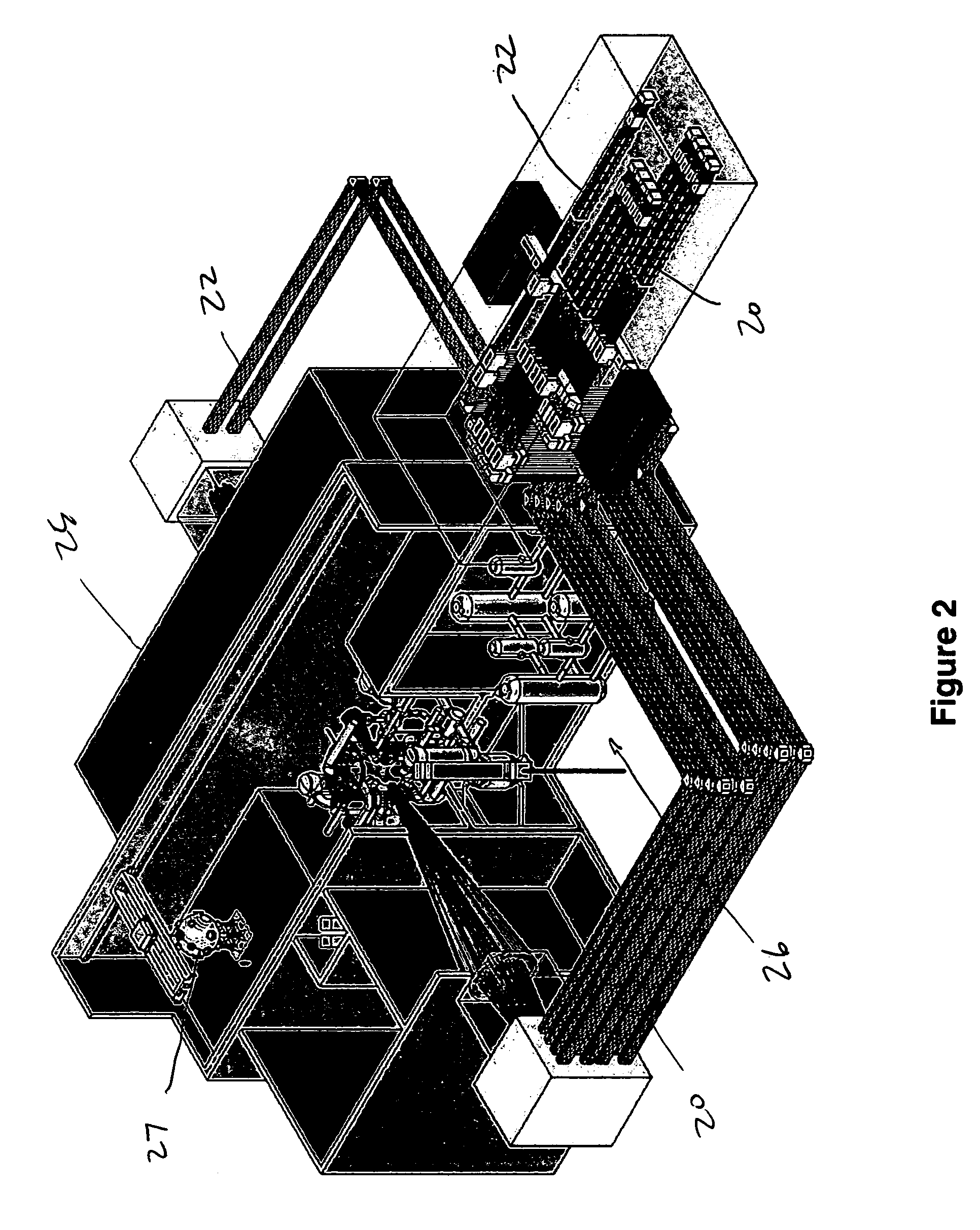
[0006]1. Overview[0007]2. Plant Layout[0008]3. Chamber[0009]4. First Wall[0010]5. Chamber Cooling System[0011]6. Fission Fuel[0012]7. Segmented Fission-Fuel Blanket[0013]8. Targets[0014]9. Laser Architecture[0015]10. Conclusion
STATEMENT AS TO RIGHTS TO INVENTIONS MADE UNDER FEDERALLY SPONSORED RESEARCH OR DEVELOPMENT
[0016]The United States Government has rights in this invention pursuant to Contract No. DE-AC52-07NA27344 between the U.S. Department of Energy and Lawrence Livermore National Security, LLC, for the operation of Lawrence Livermore National Laboratory.
I. BACKGROUND OF THE INVENTION
[0017]Projections by the Energy Information Agency and current Intergovernmental Panel on Climate Change (IPCC) expect worldwide electric power demand to double from its current level of about 2 terawatts electrical power (TWe) to 4 TWe by 2030, possibly reaching 8-10 TWe by 2100. They also expect that for the next 30 to 50 years, the bulk of the demand of electricity production will be provide...
PUM
 Abstract
Description
Claims
Application Information
 - R&D
- Intellectual Property
- Life Sciences
- Materials
- Tech Scout
- Unparalleled Data Quality
- Higher Quality Content
- 60% Fewer Hallucinations
Browse by: Latest US Patents, China's latest patents, Technical Efficacy Thesaurus, Application Domain, Technology Topic, Popular Technical Reports.
© 2025 PatSnap. All rights reserved.Legal|Privacy policy|Modern Slavery Act Transparency Statement|Sitemap|About US| Contact US: help@patsnap.com