
RFID tag

a radio frequency identification and tag technology, applied in the direction of instruments, resonant antennas, protective materials, etc., can solve the problems of increasing cost, short communication distance, not more than 1 mm, etc., and achieve the effect of reducing cos

Active Publication Date: 2015-10-27
SES RFID SOLUTIONS
View PDF16 Cites 472 Cited by
  • Summary
  • Abstract
  • Description
  • Claims
  • Application Information

AI Technical Summary

Benefits of technology

The patent describes a small RFID tag that can communicate with a distance of several cm or more. This tag is smaller and cheaper than conventional antennas, making it more practical for various applications.

Problems solved by technology

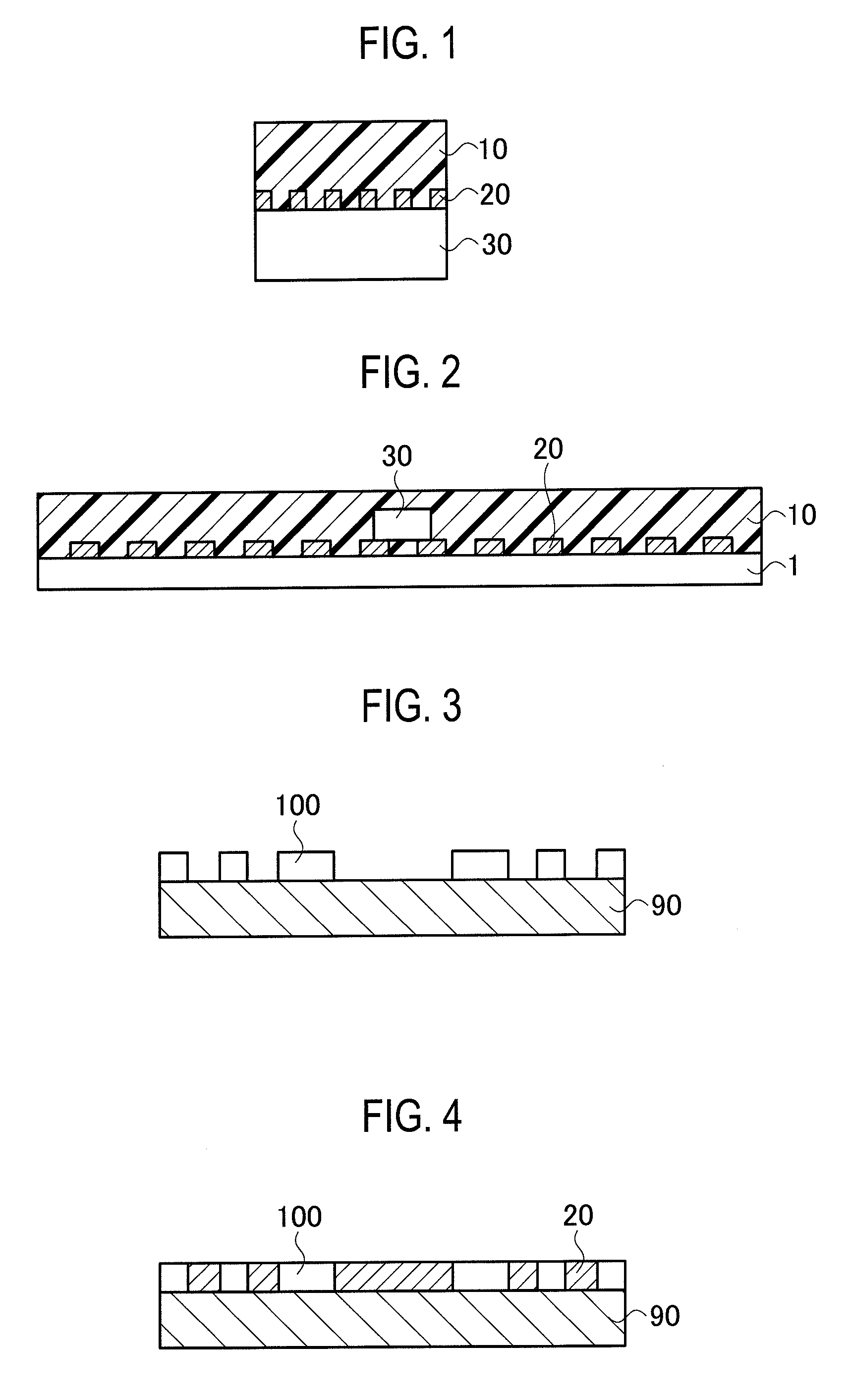
As such compact RFID tags, there is an RFID which includes an antenna (on-chip antenna) directly formed on an IC chip as illustrated in FIG. 1 but has a problem of short communication distance (not more than 1 mm).
In order to increase the communication distance of an on-chip antenna illustrated in FIG. 1, it is necessary to increase the size of the IC chip, which can increase the cost (see Patent Literatures 2 and 3).

Method used


Image

  • RFID tag
  • RFID tag
  • RFID tag

Examples


examples

Reading Evaluation Method and Experiment Results

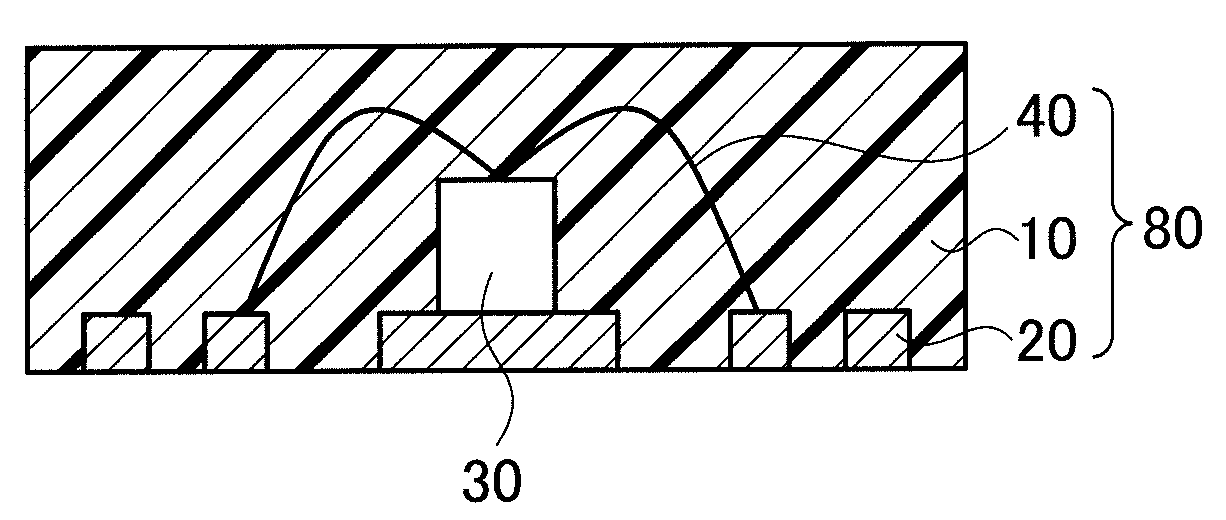
[0062]The used reader writer was UI-9061 (output: 1 W) made by LSIS Co., Ltd. The reading evaluation of the RFID tag 80 was performed with no obstacles in an area 25 cm square around the reading unit of the reader / writer. Measurement was performed in terms of the maximum distance between the reading unit of the reader / writer and the RFID tag 80 at which the reader / writer could read the RFID tag 80 (hereinafter, referred to as reading distance). Each IC chip used in the evaluation had a size of about 0.5 by 0.5 by 0.1 mm, a capacitance of 0.77 pF, and an operation frequency of about 0.86 to 0.96 GHz.

[0063]Table 1 includes results showing values obtained by measuring samples when the reading distance was the longest, each sample being obtained by forming the antenna 20 on a polyimide substrate 1 by etching, wire-bonding the IC chip 30 operating in the UHF band, and then sealing the same as illustrated in FIG. 11.

[0064]In Table 1, the res...


PUM


Abstract

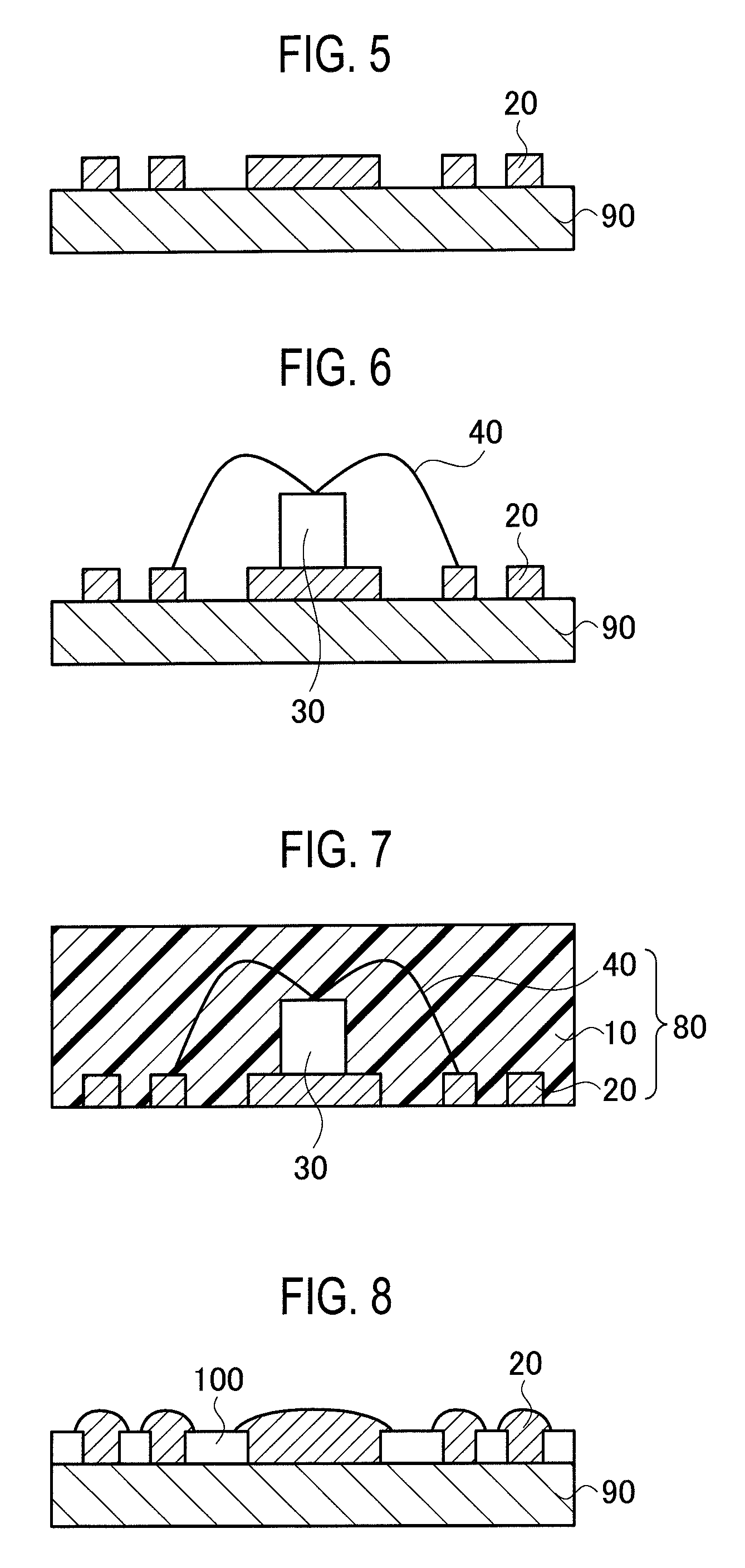
Provided is an RFID tag, wherein a communication distance of several centimeter or more can be secured and the cost of which can be reduced in comparison to conventional on-chip antennas, even when being compact in size (square shaped with a side of 1.9 to 13 mm). The RFID tag (80) comprises an antenna (20), an IC chip (30) connected to the antenna (20), and a sealing material (10) that seals the IC chip (30) and the antenna (20). The antenna (20) is a coil antenna or a loop antenna, and the resonance frequency (f0) of an electric circuit constituted by the inductance (L) of the antenna (20) and the capacitance (C) of the IC chip (30) is equal to the operation frequency of the IC chip (30), or in the vicinity thereof.

Description

TECHNICAL FIELD[0001]The present invention relates to a radio frequency identification (RFID) tag transmitting and receiving information in non contact manner in cooperation with a reader / writer.BACKGROUND ART[0002]For the purpose of identifying and managing product information and preventing counterfeiting, many non-contact RFID tags including IC chips are used in commercial goods, packages, cards, documents, and the like. IC chips includes relevant information such as name and price of commercial goods. In some IC chips, information such as manufacturing date and factory or balance can be written by a reader / writer at a later date as needed. The information written in IC chips is read by a reader / writer to be used for management, sale, and use of commercial goods. In such a manner, the RFID tags have great benefits in increasing the convenience of merchandise management, increasing security, and preventing human errors (see Patent Literature 1).[0003]RFID tags are usually attached...

Claims


Application Information

Patent Timeline
Patent Type & Authority Patents(United States)
IPC IPC(8): G06K19/077H01Q1/40H01Q1/36H01L23/31H01L21/56H01Q1/22H01Q7/00H01Q9/26H01Q1/44
CPCG06K19/07754G06K19/07749G06K19/07775G06K19/07783H01L21/56H01L23/3142H01Q1/2208H01Q1/36H01Q1/40H01Q1/44H01Q7/00H01Q9/26H01L2224/48091H01L2224/48247H01L2924/00014H01L2924/181H01L2924/00012
Inventor ENDOU, TOSHIHIROISHIZAKA, HIRONORIOOTA, MASAHIKOTASAKI, KOUJIHOSOI, HIROYUKIKAKUTA, JONARITA, HIROAKISATO, HIROKI
Owner SES RFID SOLUTIONS
Learn More