
Method and apparatus for sensing noise signals in a wireline communications environment

a technology of noise signal and wireline communication, applied in the field of wireline communications, can solve the problems of affecting the reliability of the wan interface, most domestic noise sources find their way, and the imbalance of the cable that drives the conversion of cm noise to dm as perceived by the modem is likely to be different, so as to achieve the effect of reducing the impact of dsl lines

Inactive Publication Date: 2015-10-20
IKANOS COMMUNICATIONS
View PDF12 Cites 2 Cited by
  • Summary
  • Abstract
  • Description
  • Claims
  • Application Information

AI Technical Summary

Benefits of technology

[0014]The present invention relates to methods and apparatuses for sensing noise sources in a wireline communications environment such as a customer premises environment in a DSL system. In embodiments, the invention includes an additional sensor that is connected to power mains in a DSL customer premises environment either to characterize, at their source, noises coupling into the DSL lines, and / or to mitigate their impact into the DSL lines. One objective is associated with diagnostics that help to better characterize the noise signals themselves and derive correlation of signals sensed from the power mains and their possible projection onto the DSL line. Another objective makes use of these power line sensor signals to mitigate or to eliminate power line noises that make their way onto the DSL line. Example embodiments further include and exploit signals from additional secondary sensors such as secondary common mode, differential mode and phantom mode sensors.

Problems solved by technology

In a DSL deployment, stationary and impulsive noises are generated within the home environment, which impact the reliability of the WAN interface of a residential device delivering network services such as IPTV.
But it is expected that most of the domestic noise sources find their way to the DSL line due to capacitive coupling between the mains network and the twisted pair, rather than through radiation.
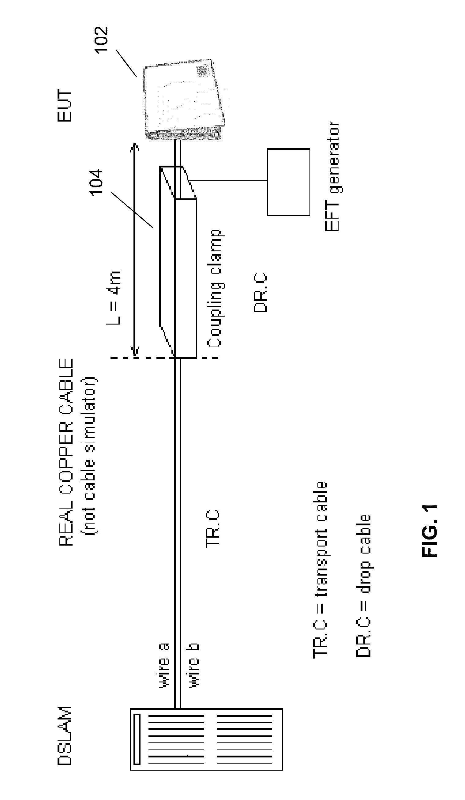
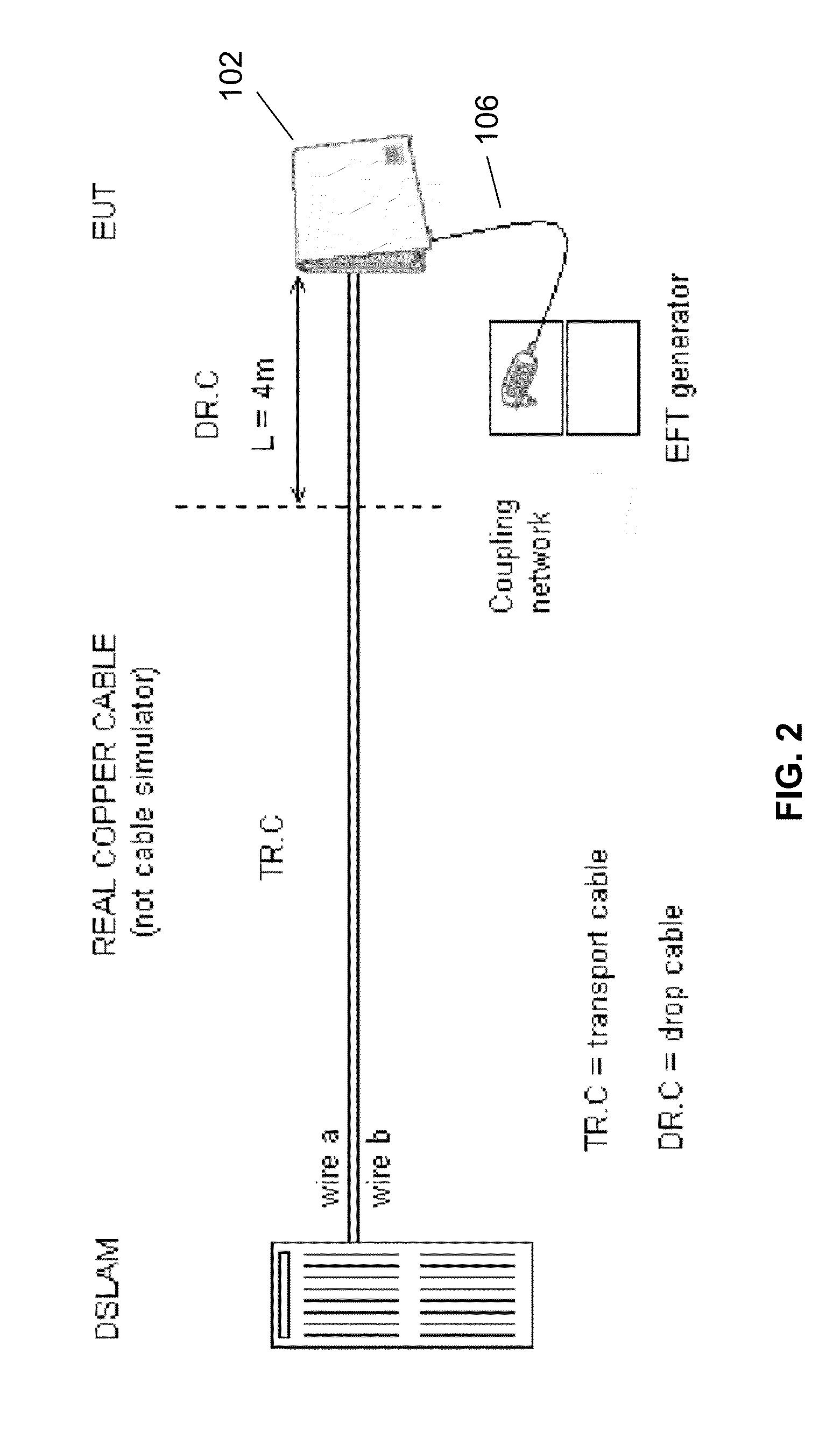
In actual field scenarios, however, the injection of the EFT signals takes place simultaneously through capacitive coupling and power supply leakage, since the EFT signals are expected to impact both interfaces of the modem simultaneously.
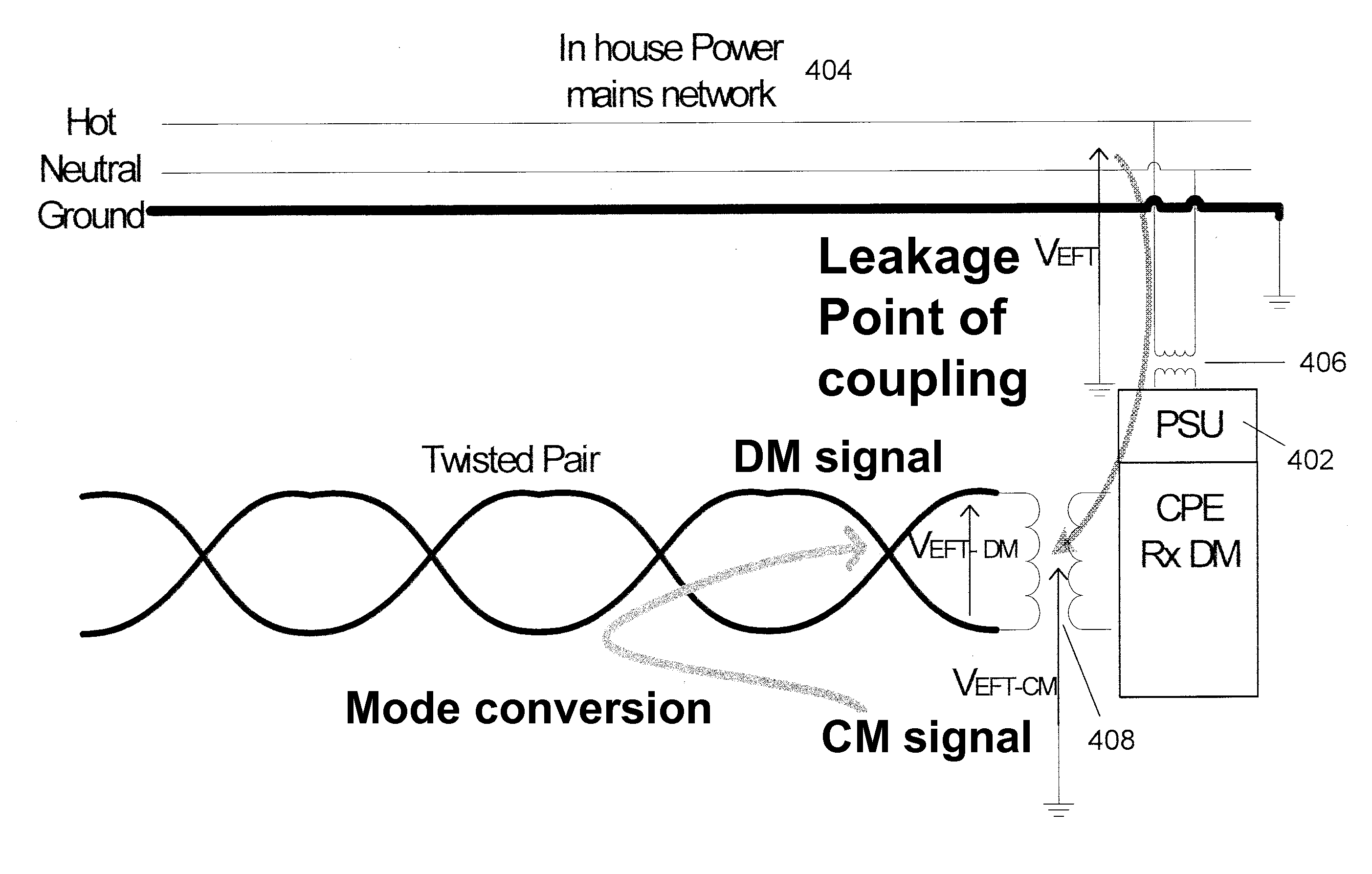
This situation just illustrates the fact that any modem (i.e. DSL link) may be susceptible to environmental interference on any of its physical interfaces (e.g. TP port, Power Supply port, Ethernet port, Serial port, etc.) In this event, whenever two coupling paths exist together between the power mains and the DSL loop, either through the capacitive coupling of the loop (FIG. 3) or through the leakage of the power supply (FIG. 4), the resulting DM noise on the DSL pair is actually a superposition of two separate noises which couple to the CM mode on the twisted pair, and then to DM through different transfer functions. FIGS. 3 and 4 illustrate that the CM to DM conversion of the signals that take place on the loop will be determined by two different mode conversion transfer functions, which will be different in the two cases due to the exact point of injection of the CM signal resulting from the coupling of the power mains noise.
4)), the imbalance of the cable that drives the conversion of the CM noise to DM as perceived by the modem is likely to be different.
This situation is an illustration that in practice, noise sources that are effectively present on the power supply mains may find their way into the DSL port through power supply leakage.

Method used


Image

  • Method and apparatus for sensing noise signals in a wireline communications environment
  • Method and apparatus for sensing noise signals in a wireline communications environment
  • Method and apparatus for sensing noise signals in a wireline communications environment

Examples


Embodiment Construction

[0038]The present invention will now be described in detail with reference to the drawings, which are provided as illustrative examples of the invention so as to enable those skilled in the art to practice the invention. Notably, the figures and examples below are not meant to limit the scope of the present invention to a single embodiment, but other embodiments are possible by way of interchange of some or all of the described or illustrated elements. Moreover, where certain elements of the present invention can be partially or fully implemented using known components, only those portions of such known components that are necessary for an understanding of the present invention will be described, and detailed descriptions of other portions of such known components will be omitted so as not to obscure the invention. Embodiments described as being implemented in software should not be limited thereto, but can include embodiments implemented in hardware, or combinations of software and...


PUM


Abstract

The present invention relates to methods and apparatuses for sensing noise sources in a wireline communications environment such as a customer premises environment in a DSL system. In embodiments, the invention includes an additional sensor that is connected to power mains in a DSL customer premises environment either to characterize, at their source, noises coupling into the DSL lines, and / or to mitigate their impact into the DSL lines. One objective is associated with diagnostics that help to better characterize the noise signals themselves and derive correlation of signals sensed from the power mains and their possible projection onto the DSL line. Another objective makes use of these power line sensor signals to mitigate or to eliminate power line noises that make their way onto the DSL line. Example embodiments further include and exploit signals from additional secondary sensors such as secondary common mode, differential mode and phantom mode sensors.

Description

CROSS REFERENCE TO RELATED APPLICATIONS[0001]This application claims priority under 35 USC 119(e) of prior U.S. Provisional Patent Application No. 61 / 715,198, filed Oct. 17, 2012, the disclosure of which is hereby incorporated by reference in its entirety.FIELD OF THE INVENTION[0002]The present invention relates generally to wireline communications, and more particularly to a sensor coupled to power lines for use in characterizing and / or mitigating noise sources in a DSL modem.BACKGROUND OF THE INVENTION[0003]In a DSL deployment, stationary and impulsive noises are generated within the home environment, which impact the reliability of the WAN interface of a residential device delivering network services such as IPTV. Sources of such disturbances include house appliances such as vacuum cleaners, lamps, or equipment such as pool pumps, washing machines, etc. Apart from Differential Mode (DM) self-FEXT signals that are expected to result primarily from a DM to DM coupling, in a house e...

Claims


Application Information

Patent Timeline
Patent Type & Authority Patents(United States)
IPC IPC(8): H04B3/46H04B3/487H04B3/32
CPCH04B3/32H04B3/46H04B3/487H04B3/466H04L12/2856
Inventor ALLOIN, LAURENT FRANCISKEASLER, JR., WILLIAM EDWARDPIERRUGUES, LAURENTMURALT, ARNOLD
Owner IKANOS COMMUNICATIONS
Learn More