
Image processing device that performs tracking control

a tracking control and image processing technology, applied in image enhancement, scene recognition, instruments, etc., can solve the problem of difficult to detect a minute change in the magnitude of the preceding vehicle on the image, and achieve the effect of accurate parameter and precise tracking control of the preceding vehicl

Active Publication Date: 2015-10-20
HITACHI LTD
View PDF31 Cites 0 Cited by
  • Summary
  • Abstract
  • Description
  • Claims
  • Application Information

AI Technical Summary

Benefits of technology

[0008]An object of the present invention is to provide an image processing device in which it is possible to obtain an accurate parameter from a minimal change of an image, and to execute a precise tracking control of a preceding vehicle using only image information from an imaging device.
[0011]According to the aspects of the invention, it is possible to provide an image processing device in which it is possible to obtain an accurate parameter from a minute change of an image, and to execute a precise tracking control of a preceding vehicle using only image information from an imaging device.

Problems solved by technology

In addition, there is a problem that it is difficult to detect a minute change of the magnitude of the preceding vehicle on the image.

Method used


Image

  • Image processing device that performs tracking control
  • Image processing device that performs tracking control
  • Image processing device that performs tracking control

Examples


first embodiment

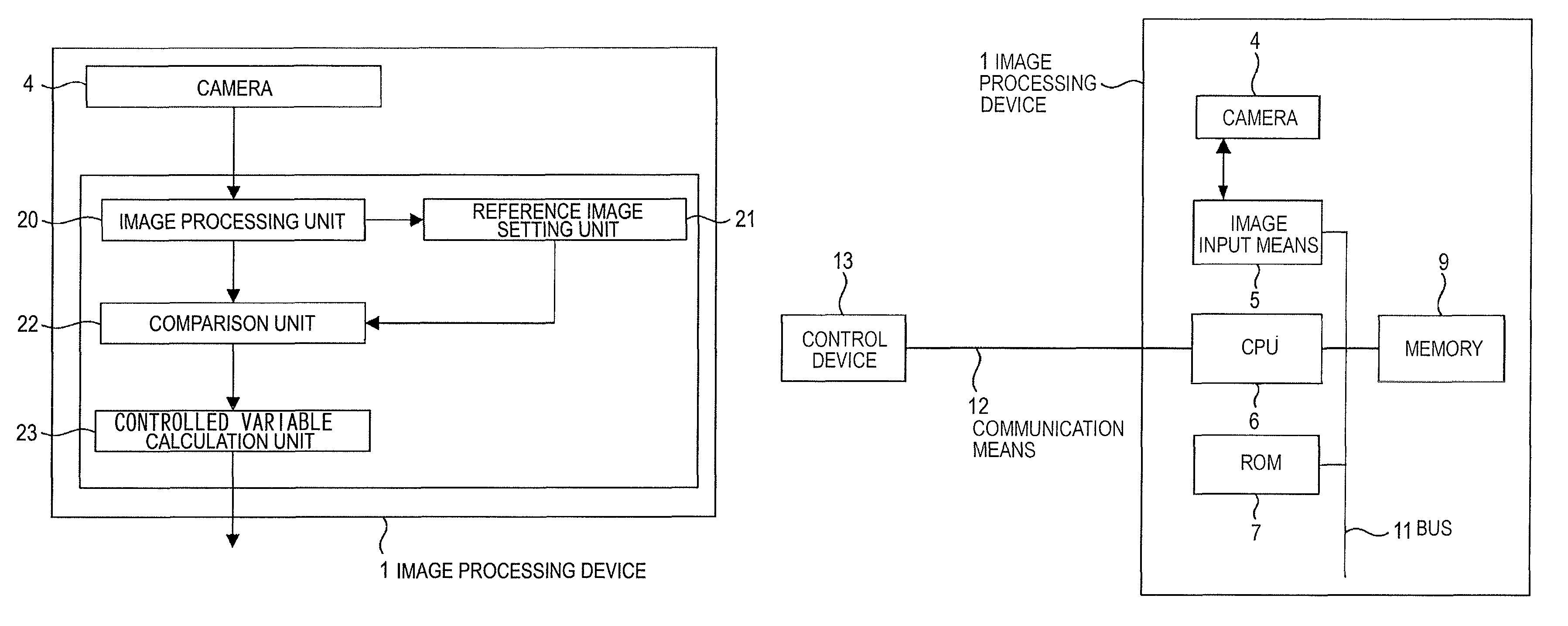
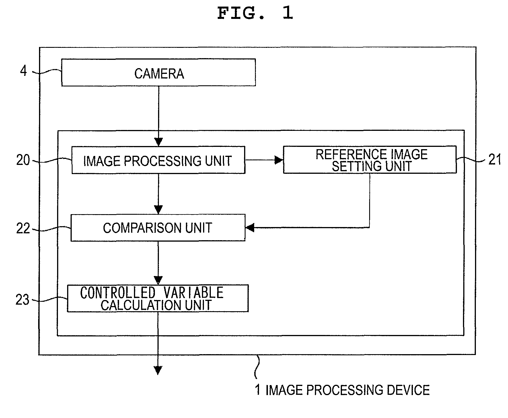
[0021]FIG. 1 is a block diagram which shows an example of a basic configuration of an image processing device 1 according to a first embodiment of the invention. Detailed descriptions will be made later.

[0022]The first embodiment is a control method of the image processing device 1 which performs processing with respect to an image read from a camera 4 as an imaging device, and performs a tracking control of a preceding vehicle as a moving object which is travelling in front of the own vehicle based on the controlled variable of the own vehicle.

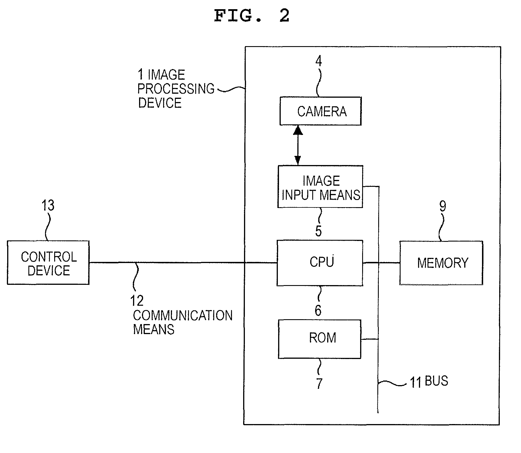
[0023]The image processing device 1 according to the invention is applied to the image processing device 1 and a control device 13 as shown in FIG. 2, images the surrounding environment using the camera 4 (imaging device) included in the image processing device 1, performs processing of an image, and executes a function of controlling a vehicle.

[0024]At this time, the image processing device 1 may be provided with two or more cameras. In addi...

second embodiment

[0076]A second embodiment of the invention will be described in detail with reference to drawings.

[0077]In the first embodiment, the example of applying the invention to the tracking control of the preceding vehicle has been described, however, it is possible to perform a control of maintaining the lane mark by using road surface paint which is present continuously, and intermittently such as a lane mark of a road.

[0078]That is, the second embodiment is configured by including, an image processing unit 20 which detects a lane mark on the road from an input image, sets an area of the detected lane mark as the reference image area, and sets an area of the lane mark after a predetermined time as a comparison image area; a comparison unit 22 which compares the set reference image area and the comparison image area with each other, and calculates a translation component of the image and a rotation parameter of the image; and a controlled variable calculation unit 23 which calculates a co...


PUM


Abstract

An image processing device which performs a tracking control with respect to a moving object which is travelling forward, based on the controlled variable of the own vehicle includes, an image processing unit which specifies an area of a moving object from an input image, sets the specified area of the moving object as a reference image area after starting tracking control, and sets an area of the moving object after a predetermined time as a comparison image area; a comparison unit which compares the set reference image area and the comparison image area with each other, and calculates travelling information relating to the moving object; and a controlled variable calculation unit which calculates a controlled variable of the own vehicle from travelling information which is calculated in the comparison unit.

Description

BACKGROUND OF THE INVENTION[0001]1. Field of the Invention[0002]The invention relates to an image processing device which performs image processing.[0003]2. Background Art[0004]In recent years, in-vehicle cameras have been developed and are becoming widespread for supporting driving. These cameras not only show a user an image, but also are provided with a function for automatically detecting a lane mark, or vehicles using imaging processing, and in which a function of preventing an accident of a vehicle departing from the lane mark, or a function of following a preceding vehicle has been developed. In general, in order to execute these two functions, radar equipment such as a mill wave radar, or a laser radar, and the in-vehicle camera are used. There is a problem of high cost since two types of sensors are used.[0005]Therefore, a technology is required in which a function of executing a tracking control, and lane mark keeping is executed only using an image obtained from the camer...

Claims


Application Information

Patent Timeline
Patent Type & Authority Patents(United States)
IPC IPC(8): H04N7/18G06T7/20G06K9/00G06K9/32
CPCG06T7/204G06K9/00798G06K9/00805G06K9/3241G06T2207/30252G06T7/248G06V20/588G06V20/58G06V10/255
Inventor HIGUCHI, MIRAIOGATA, TAKEHITOSHIMA, TAKESHI
Owner HITACHI LTD
Learn More