
Transmission system of four wheel drive hybrid electric vehicle

a hybrid electric vehicle and transmission system technology, applied in the direction of gas pressure propulsion mounting, propulsion parts, transportation and packaging, etc., can solve the problems of reducing fuel efficiency, increasing production cost, reducing power transmission efficiency, etc., and achieve the effect of saving production cos

Inactive Publication Date: 2015-10-13
HYUNDAI MOTOR CO LTD
View PDF7 Cites 3 Cited by
  • Summary
  • Abstract
  • Description
  • Claims
  • Application Information

AI Technical Summary

Benefits of technology

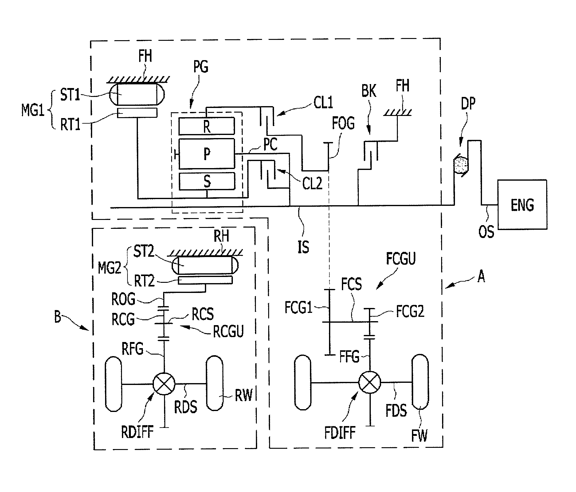
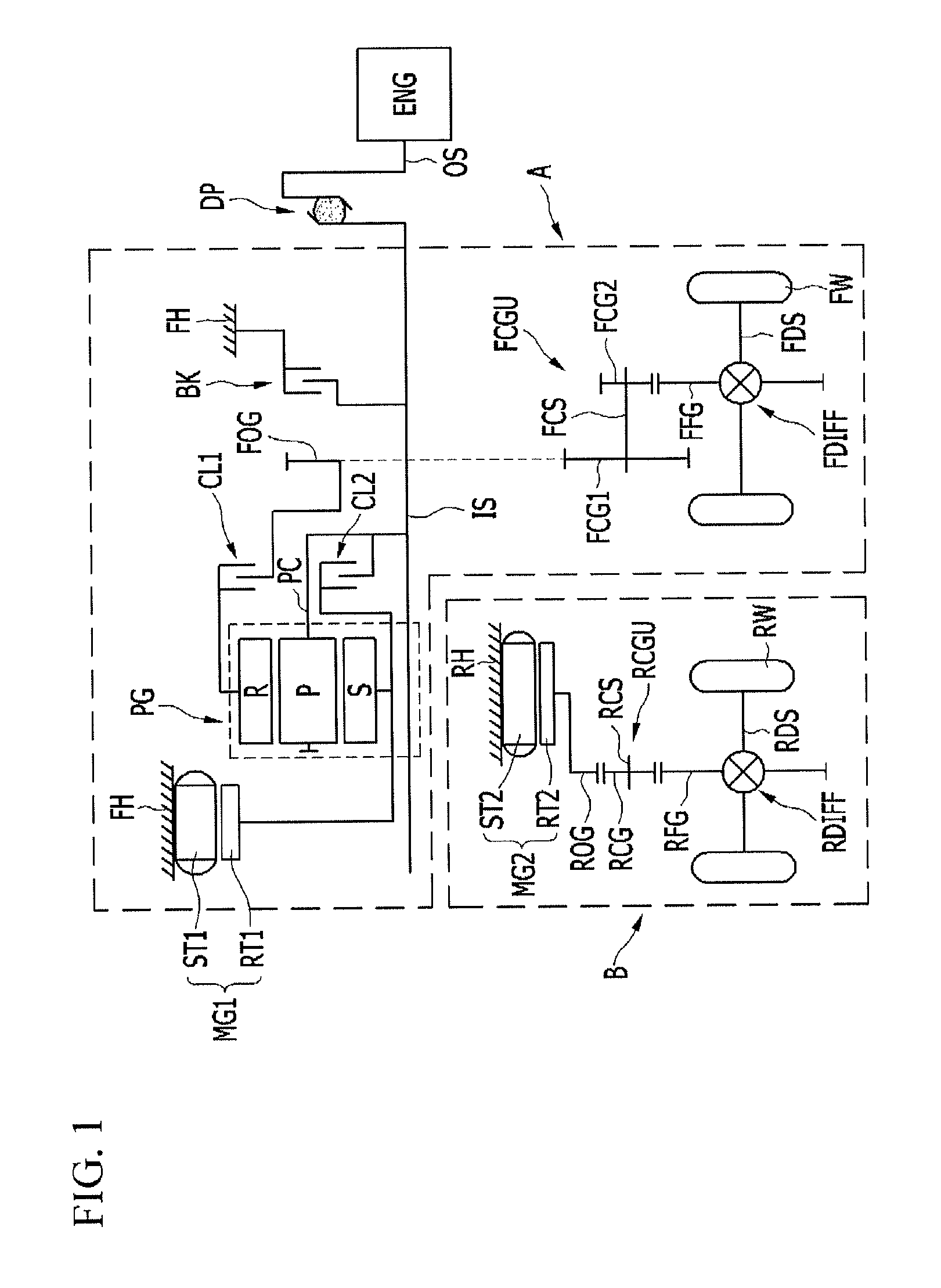
[0021]Various aspects of the present invention provide for a transmission system for a four wheel drive hybrid electric vehicle capable of saving production cost by using motor / generators less by one than in the related art.
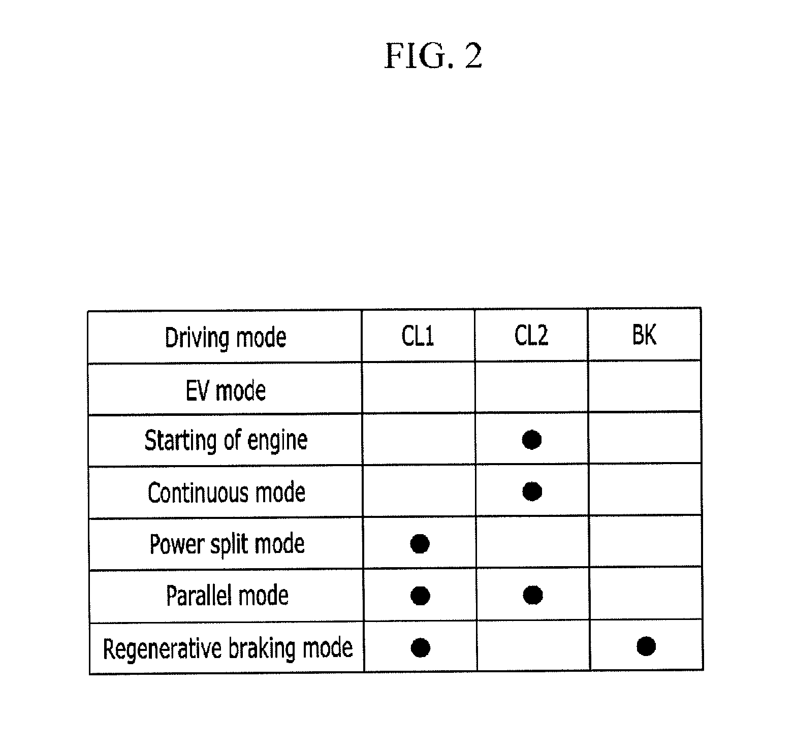
[0022]Further, various aspects of the present invention provide for a transmission system for a four wheel drive hybrid electric vehicle capable of maximizing improvement of fuel efficiency by performing driving of a power split mode having better low-speed driving efficiency and a parallel mode having better high-speed driving efficiency.
[0023]Further, various aspects of the present invention have been made in an effort to provide a transmission system for a four wheel drive hybrid electric vehicle capable of saving production cost by reducing a capacity of a motor / generator for generation using a power split mode.

Problems solved by technology

The single mode type may not require connection units, such as a clutch and a brake for transmission control, but may have the reduced fuel efficiency at the time of high-speed driving and require an additional torque multiplication apparatus so as to apply to a large vehicle.
Therefore, in order to supplement the above problem, there is a need to increase the number of planetary gear sets and the number of clutches and brakes, which may lead to reduced power transmission efficiency and increased production cost.

Method used


Image

  • Transmission system of four wheel drive hybrid electric vehicle
  • Transmission system of four wheel drive hybrid electric vehicle
  • Transmission system of four wheel drive hybrid electric vehicle

Examples


Embodiment Construction

[0042]Reference will now be made in detail to various embodiments of the present invention(s), examples of which are illustrated in the accompanying drawings and described below. While the invention(s) will be described in conjunction with exemplary embodiments, it will be understood that present description is not intended to limit the invention(s) to those exemplary embodiments. On the contrary, the invention(s) is / are intended to cover not only the exemplary embodiments, but also various alternatives, modifications, equivalents and other embodiments, which may be included within the spirit and scope of the invention as defined by the appended claims.

[0043]Accordingly, the drawings and description are to be regarded as illustrative in nature and not restrictive. Like reference numerals designate like elements throughout the specification.

[0044]In the following description, the same components are classified into first, second, and the like to differentiate names for components and...


PUM


Abstract

A transmission system for a four wheel drive hybrid electric vehicle includes: an input shaft selectively connected to a front wheel transmission housing while being connected to an output shaft of an engine; a first motor / generator having disposed in the front wheel transmission housing; a second motor / generator having a function of the motor and the generator and connected to a rear wheel output gear disposed in a rear wheel transmission housing; a planetary gear set on the input shaft and including three rotating elements, in which among three rotating elements, a first rotating element is directly connected to the first motor / generator and selectively connected to the input shaft, a second rotating element is directly connected to the input shaft, and a third rotating element is selectively connected to a front wheel output gear; and a connection unit disposed at a selective connection part.

Description

CROSS-REFERENCE TO RELATED APPLICATION[0001]The present application claims priority of Korean Patent Application Number 10-2013-0119315 filed Oct. 7, 2013, the entire contents of which application is incorporated herein for all purposes by this reference.BACKGROUND OF INVENTION[0002]1. Field of Invention[0003]The present invention relates to a transmission system for a four wheel drive hybrid electric vehicle, and more particularly, to a transmission system for a four wheel drive hybrid electric vehicle capable of maximizing improvement of fuel efficiency by performing driving of a power split mode having better low-speed driving efficiency and a parallel mode having better high-speed driving efficiency.[0004]2. Description of Related Art[0005]Generally, a hybrid electric vehicle is a vehicle which is driven by effectively combining at least two different kinds of power sources.[0006]The hybrid electric vehicle generally uses an engine and a motor / generator, and uses the motor / gener...

Claims


Application Information

Patent Timeline
Patent Type & Authority Patents(United States)
IPC IPC(8): B60K6/52B60K6/387B60K6/44B60K6/445B60W20/00B60K6/38
CPCB60K6/52B60K6/387B60K6/445B60W20/10B60K6/44B60K2006/381Y02T10/62B60K6/36B60K6/38B60K6/42
Inventor CHOI, KUM LIMKIM, KYOUNG JOOCHO, JINKUK
Owner HYUNDAI MOTOR CO LTD
Learn More