
Single screw extruder

a single screw and extruder technology, applied in mixers, baking, dough mixing/kneading machines, etc., can solve the problems of non-melted residual solid matter, affecting the quality of melt, and the shear section cannot fulfil the actual task, so as to achieve excellent product quality, high overall throughput, and high melting performance of single screw extruder according to the invention

Active Publication Date: 2015-10-13
KRAUSSMAFFEI EXTRUSION GMBH
View PDF21 Cites 11 Cited by
  • Summary
  • Abstract
  • Description
  • Claims
  • Application Information

AI Technical Summary

Benefits of technology

The invention is a single screw extruder that improves melting and residual melting, while increasing throughput, reducing melt temperature, and improving pressure build-up.

Problems solved by technology

However, disadvantages also result through the fact that the maddock or barrier shear section are mounted rotatably here in a grooved cylinder section.
By the passage of the residual solid matter into the melt in adjacent channels of the shear section, the residual solid matter can in fact be well heated on the one hand and at the same time the surrounding melt can be cooled, but on the other hand the danger also exists that non-melted residual solid matter leaves the extruder with the melt and thus impairs the quality of the melt.
The shear section therefore can not fulfil its actual task, namely to retain residual solid matter contained in the raw melt and to plasticize this under the effect of moderate shear deformation in the shear gap between cross-pieces of the shear section and the inner wall of the cylinder.

Method used


Image

  • Single screw extruder
  • Single screw extruder

Examples


Embodiment Construction

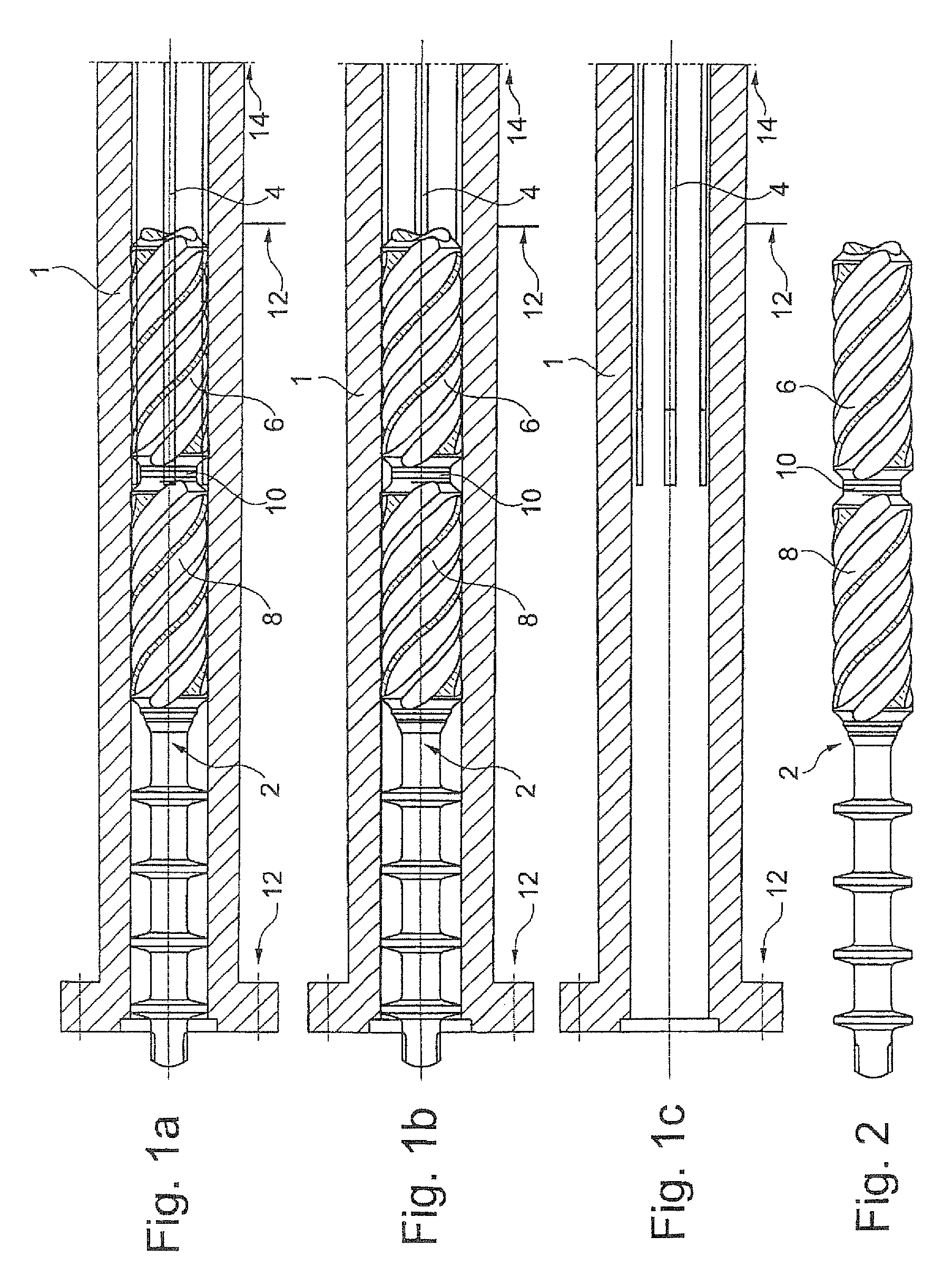
[0030]In FIG. 1a a section of a cylinder 1 of a single screw extruder according to the invention is illustrated diagrammatically in section, wherein the homogenizing zone 12 and a region of the melting zone 14 are illustrated. A section of a screw 2 is contained in the cylinder 1, the end of which screw on the conveying direction side is on the left-hand side in the figure and continues towards the right into the melting region, but is illustrated here in broken form. The screw is illustrated in broken form so that one can see through it onto the inner wall of the cylinder. The inner wall of the cylinder is provided with grooves 4 which run in the figure in longitudinal direction and in the present case are situated both in a region of the homogenizing zone 12 and also in the melting zone 14, wherein they extend from the region of the homogenizing zone 12, without a transitional stage, into the melting zone 14. In the homogenizing zone 12, the grooves 4 end in the region between a f...


PUM

PropertyMeasurementUnit
Shapeaaaaaaaaaa
Depthaaaaaaaaaa

Abstract

The invention relates to a single-screw extruder comprising a cylinder (1), which comprises a transition zone (14), and a homogenizing zone (12) that is connected to the transition zone (14), and a screw (2) which is rotatably supported in the cylinder (1) and which has at least two consecutive displacement parts (6, 8) in the homogenizing zone (12), the second displacement part of which in the conveying direction is designed as a shearing part. The aim of the invention is to provide a single-screw extruder which enables an improved melting effect along with an increased throughput, a lowered melt temperature, and an improved pressurization capability. According to the invention, it was recognized that this aim can be achieved in that at least one groove (4) running in the longitudinal direction in the inner cylinder wall is provided in the homogenization zone (12) of the single-screw extruder, and said groove ends in the area between a first displacement part and the subsequent shearing part (8) as viewed in the conveying direction.

Description

CROSS-REFERENCES TO RELATED APPLICATIONS[0001]This application is the U.S. National Stage of International Application No. PCT / EP20091058612, filed Jul. 7, 2009, which designated the United States and has been published as International Publication No. WO 2010 / 020467 and which claims the priority of German Patent Application, Serial No. 10 2008 038 529.8, filed Aug. 20, 2008, pursuant to 35 U.S.C. 119(a)-(d).BACKGROUND OF THE INVENTION[0002]The present invention relates to a single screw extruder with a cylinder which has a melting zone and a homogenizing zone, which adjoins the melting zone, and a screw mounted rotatably in the cylinder, which has at least two process sections, following each other, in the region of the homogenizing zone, the second of which in the conveying direction is constructed as a shear section.[0003]In known single screw extruders it is a constant task of the specialist in the art to increase the throughput of the single screw extruder, at the same time mai...

Claims


Application Information

Patent Timeline
IPC IPC(8): B29C47/38B29C47/58B29C47/60B29C47/64B29C47/66B29B7/42B29C47/62B29C47/00B29C48/03B29C48/395B29C48/50B29C48/53B29C48/56B29C48/575B29C48/65B29C48/67B29C48/68
CPCB29C47/625B29C47/64B29C47/66B29C47/666B29C47/6062B29C47/38B29C47/385B29C47/585B29C47/6018B29C47/6043B29B7/42B29C47/0009B29C48/686B29C48/53B29C48/56B29C48/65B29C48/67B29C48/68B29C48/395B29C48/397B29C48/501B29C48/575B29C48/03
Inventor SCHNEIDER, FLORIAN JOHANNES
Owner KRAUSSMAFFEI EXTRUSION GMBH
Learn More