
Scenting nebulizer with remote management and capacitive liquid level sensing

a capacitive liquid level and scenting nebulizer technology, applied in the field of electronic liquid level sensors, can solve the problems of user believing the system is broken, the scenting oil level can get low and run out, and the majority of these scenting nebulizers are mounted in hard to reach places, so as to achieve the effect of reducing maintenance services

Inactive Publication Date: 2015-10-06
PICA PROD DEV
View PDF15 Cites 5 Cited by
  • Summary
  • Abstract
  • Description
  • Claims
  • Application Information

AI Technical Summary

Benefits of technology

The invention is a scenting nebulizer with a microprocessor-controlled oil pump and a level detection system that does not physically contact the oil in the nebulizer. This eliminates the need for maintenance and minimizes fouling of the oil level sensor. The nebulizer also has keys for controlling its operation and a display for showing operational indications. A central computer can monitor and control multiple scenting nebulizers located at different physical locations, eliminating the need for manual checking of oil levels. This allows service providers to manage a network of nebulizers more efficiently, detect and address potential problems quickly, and minimize downtime.

Problems solved by technology

Currently most public and professional establishments that utilize a scenting nebulizer have no remote management of the nebulizer operational settings or an easy way to check scenting oil levels in the nebulizer.
In addition, most of these scenting nebulizers are mounted in hard to reach places, for example, near or inside an HVAC system or high on shelves or in ceilings.
Scenting oil levels can get low and run out which causes a support issue where the end-user believes the system is broken; and an intended use issue where the scenting nebulizer is not scenting creating a negative revenue generating environment.

Method used


Image

  • Scenting nebulizer with remote management and capacitive liquid level sensing
  • Scenting nebulizer with remote management and capacitive liquid level sensing
  • Scenting nebulizer with remote management and capacitive liquid level sensing

Examples


Embodiment Construction

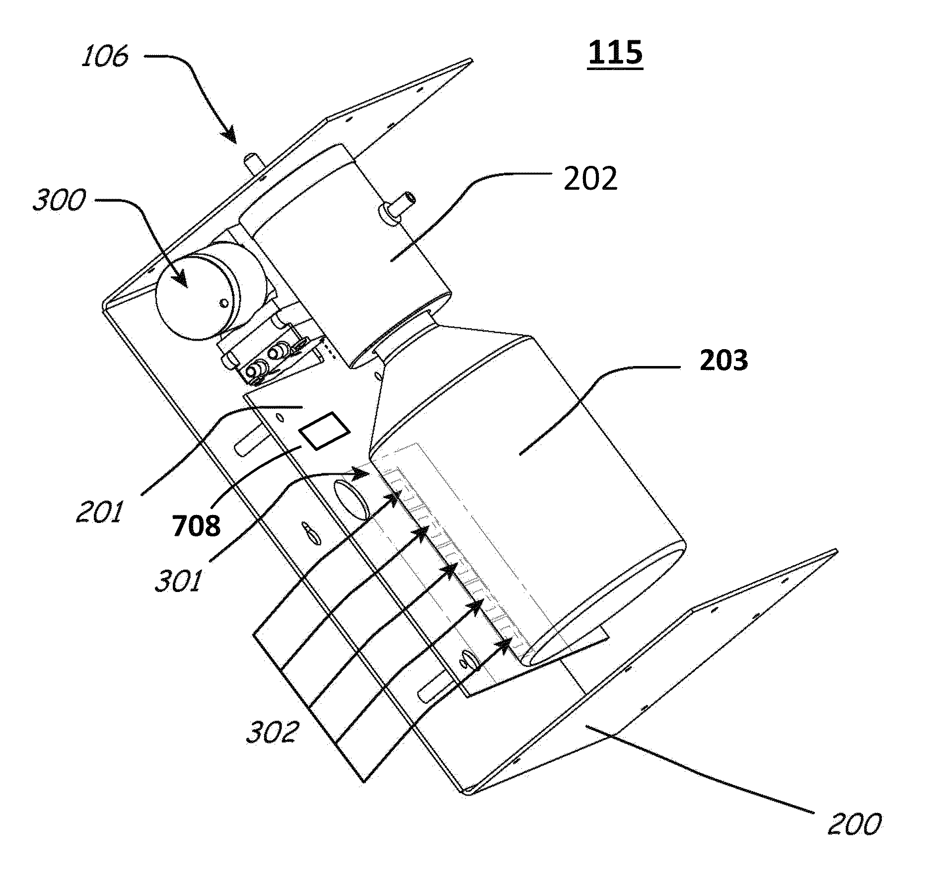
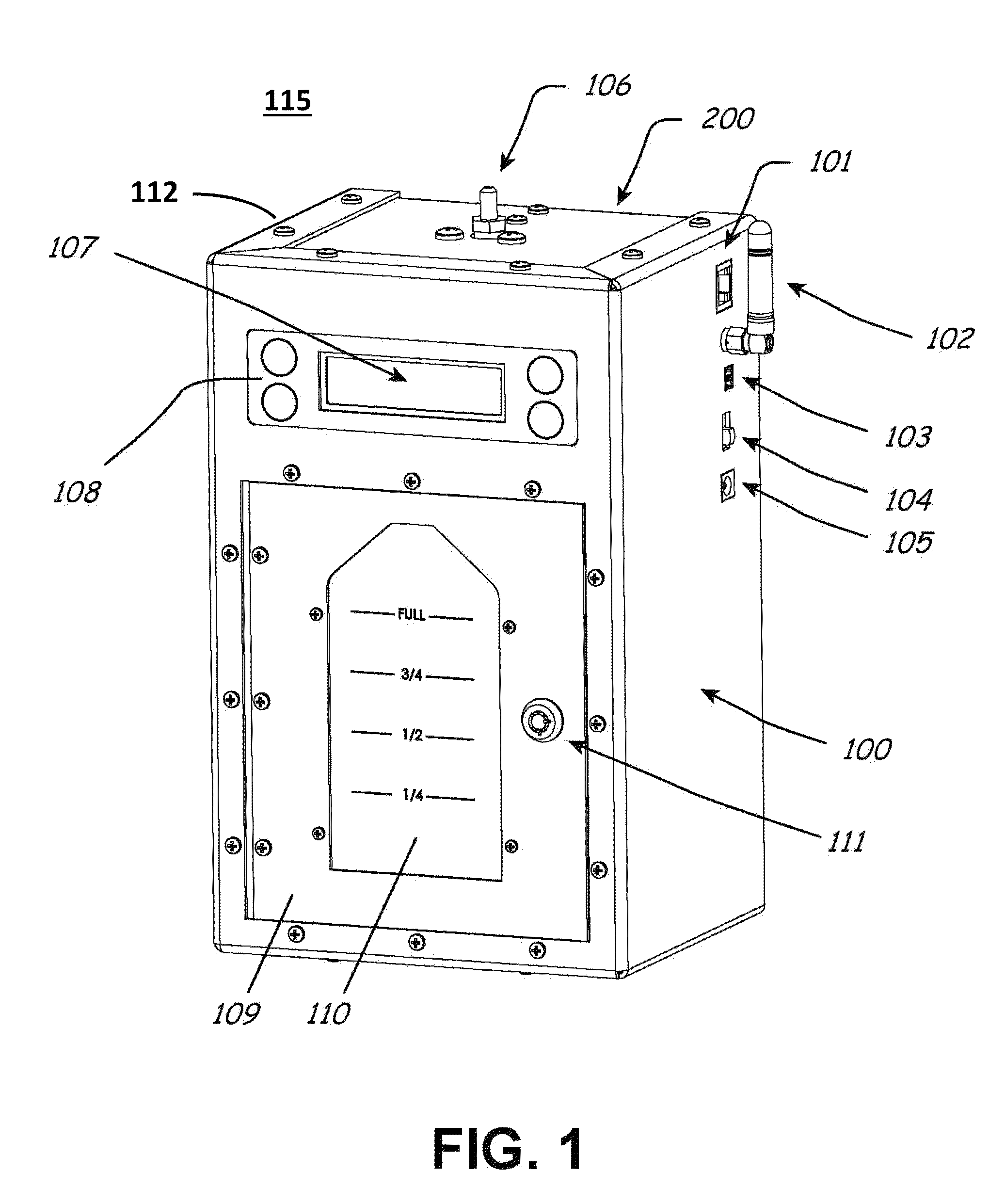
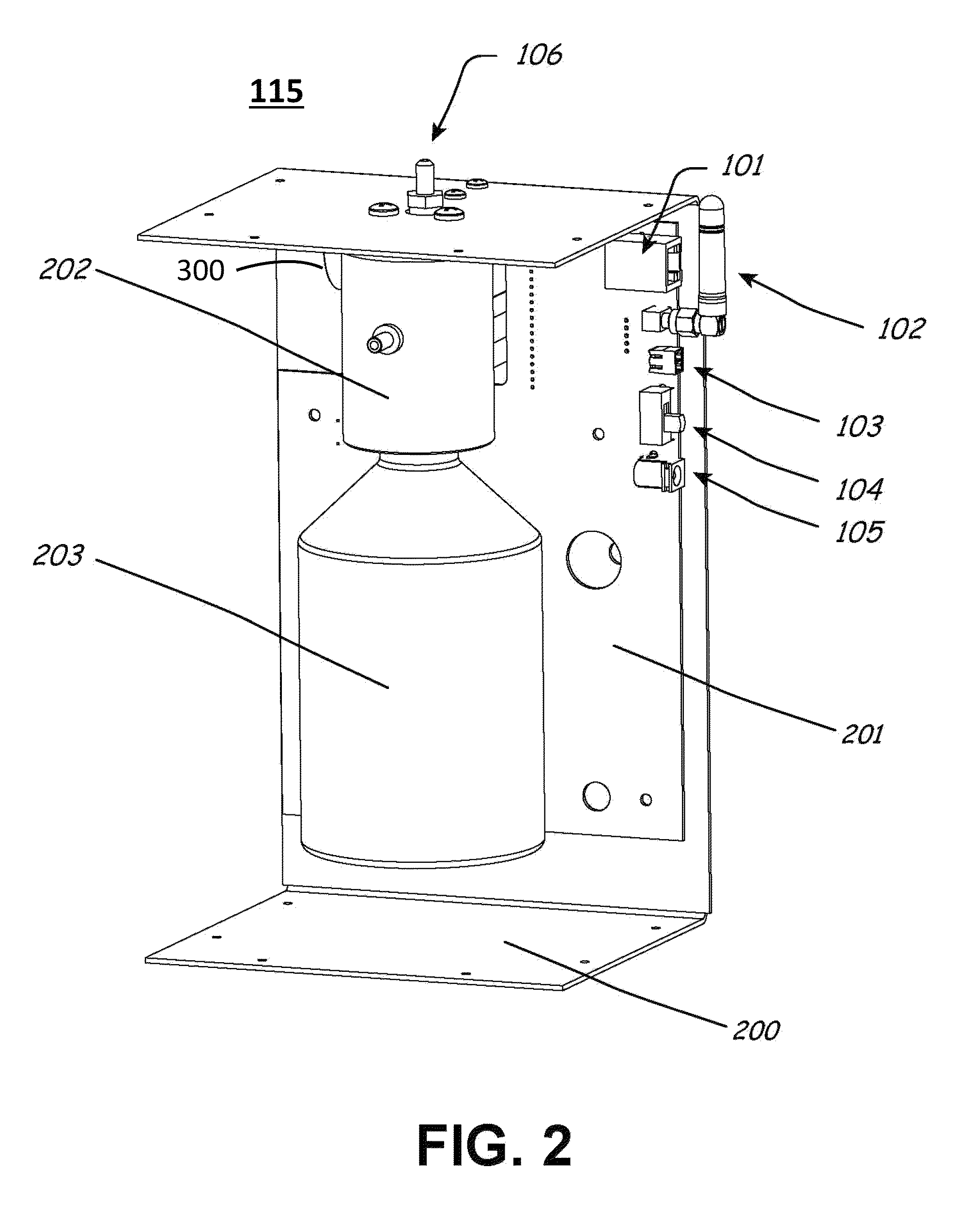
[0026]A preferred embodiment of the novel scenting nebulizer 115 is shown in the Figures for the distribution by nebulization of scented oil and utilizing the novel capacitive liquid level sensor to monitor the level of scenting oil in a bottle 203 of the scenting nebulizer 115. This level sensing is done without contacting the scenting oil, and also provides an appropriate oil level indication that is continuously monitored and used to prevent running out of scenting oil.

[0027]Referring to FIG. 1, the outer construction of scenting nebulizer 115 consists of a top or front cover 100 and a base housing 200, both made of metal with a special chemically resistant powder coating. Top cover 100 is removed from bottom 200 by removing screws 112 such as those shown through the edges of top cover 100 as shown in FIG. 1. Localized user programming of the operation of a scenting device 115 is accomplished by using a membrane keyboard 108 and an LCD display 107. Display 107 may also be used to...


PUM


Abstract

A scenting nebulizer is described that capacitively measures the level of scenting oil in a bottle in the nebulizer without ever contacting the oil in the bottle. In addition, such capacitively measured oil levels are measured at multiple vertical levels of the bottle of scenting oil. In actual operation the capacitively measured oil level readings are very frequently measured then averaged, and the averaged figures are stored. The stored, averaged figures are interpolated against previously stored, capacitance readings made when the scenting oil bottle is full and when there is no bottle. In this manner the level of the oil is accurately determined. A plurality of processor controlled scenting nebulizers are connected to a central computer and their individual oil levels and other operational information are forwarded to the central computer where appropriate maintenance for the individual nebulizers is scheduled. The operational settings operation of the nebulizers may be programmed from the central computer.

Description

RELATED APPLICATIONS[0001]This application claims the benefit of U.S. Provisional Application 62 / 151,529 filed Apr. 23, 2015, which is incorporated herein in its entirety by reference.FIELD OF THE INVENTION[0002]The invention relates to electronic liquid level sensors and, particularly, to a capacitive liquid level sensor that is functioning with a local microprocessor both used in a scenting nebulizer to monitor the level of scenting oil in a container inside the nebulizer in a way that does not physically contact the oil. The invention also relates to a centralized computer that monitors the operation of and the level of scenting oil in each of a plurality of remote scenting nebulizers and provides a warning signal when a problem is detected and / or the capacitive liquid level sensors of the nebulizers detect that the level of scenting oil in the nebulizer is low. The centralized computer also monitors the operating settings of the nebulizers and is used to program their operationa...

Claims


Application Information

Patent Timeline
Patent Type & Authority Patents(United States)
IPC IPC(8): G01F23/26G08B21/18
CPCG08B21/182G01F23/266G01F23/268G01F23/265A61L9/14A61L2209/111A61L2209/12A61L2209/16G01F23/804
Inventor STAPLEFORD, SCOTT
Owner PICA PROD DEV
Learn More