Developing apparatus
a technology of developing apparatus and development surface, applied in the direction of electrographic process apparatus, instruments, optics, etc., can solve the problems of uneven shading, adverse effects, and inability to evenly spread the surface of the developer, and achieve the effect of suppressing troubles
- Summary
- Abstract
- Description
- Claims
- Application Information
AI Technical Summary
Benefits of technology
Problems solved by technology
Method used
Image
Examples
first embodiment
Image Forming Apparatus
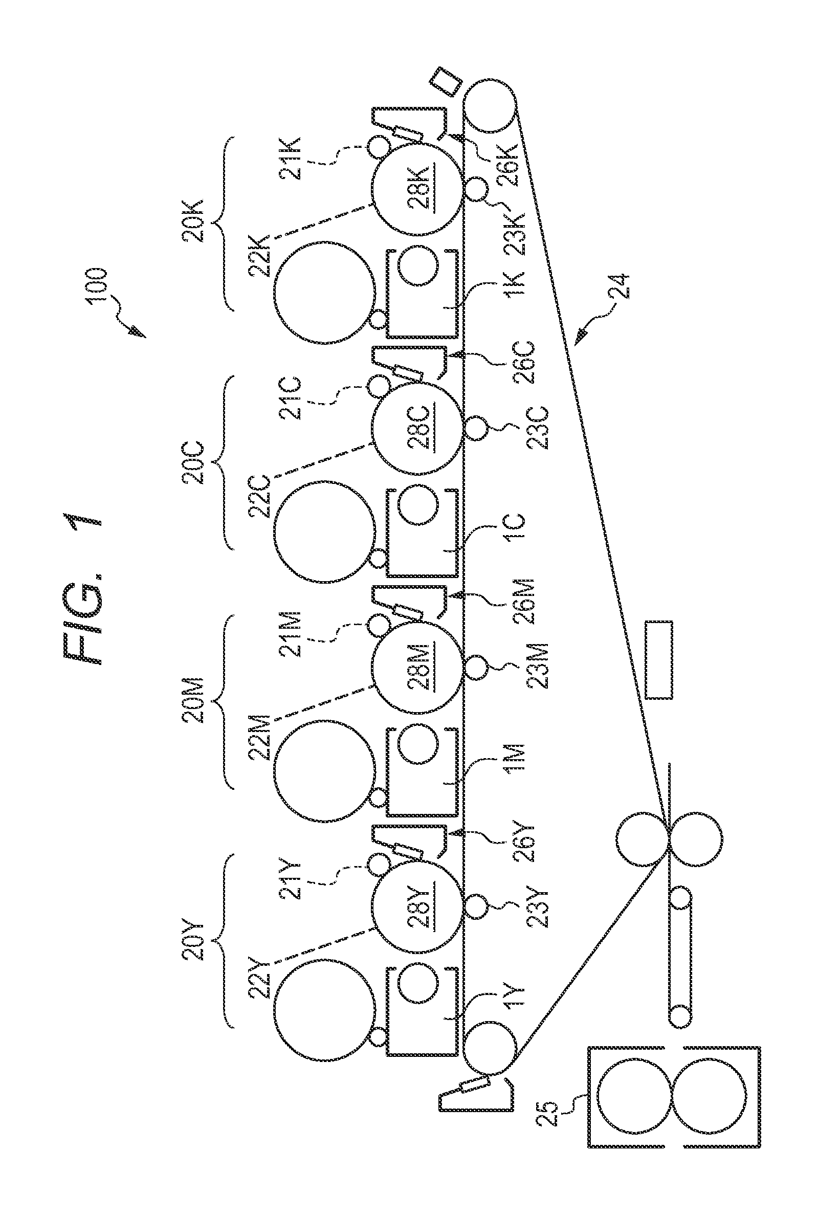
[0045]As illustrated in FIG. 1, a developing apparatus 1 according to the embodiment is used in a full-color image forming apparatus 100 of a so-called tandem type. The image forming apparatus 100 includes, as image forming portions, a yellow station 20Y, a magenta station 20M, a cyan station 20C, and a black station 20K. Drum cartridges configured to perform toner image forming steps of those four colors, that is, yellow, magenta, cyan, and black, are provided in parallel to each other. Toner images of those four colors are superimposed on each other on an intermediate transfer belt 24, transferred collectively onto a transfer sheet, and then pressurized and heated by a fixing device 25. In this way, a full-color image is obtained. Note that, in the following description, components common to the drum cartridges of yellow, magenta, cyan, and black in FIG. 1 are denoted by reference numerals without suffixes “Y,”“M,”“C,” and “K.”
[0046]With reference to FIG. 1,...
second embodiment
[0059]In the embodiment, a more preferred position of the scooping magnetic pole is specified. Other configuration features than the arrangement of the scooping magnetic pole are the same as those in the first embodiment, and hence are not described in detail. In the embodiment, only the differences from the first embodiment will be described.
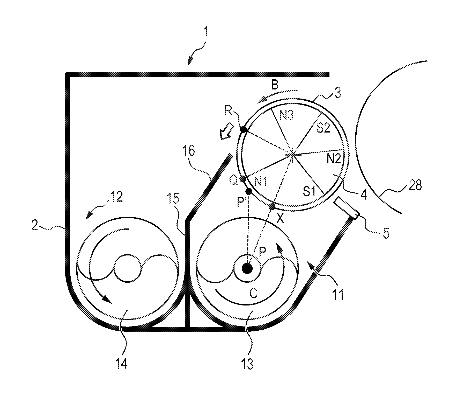
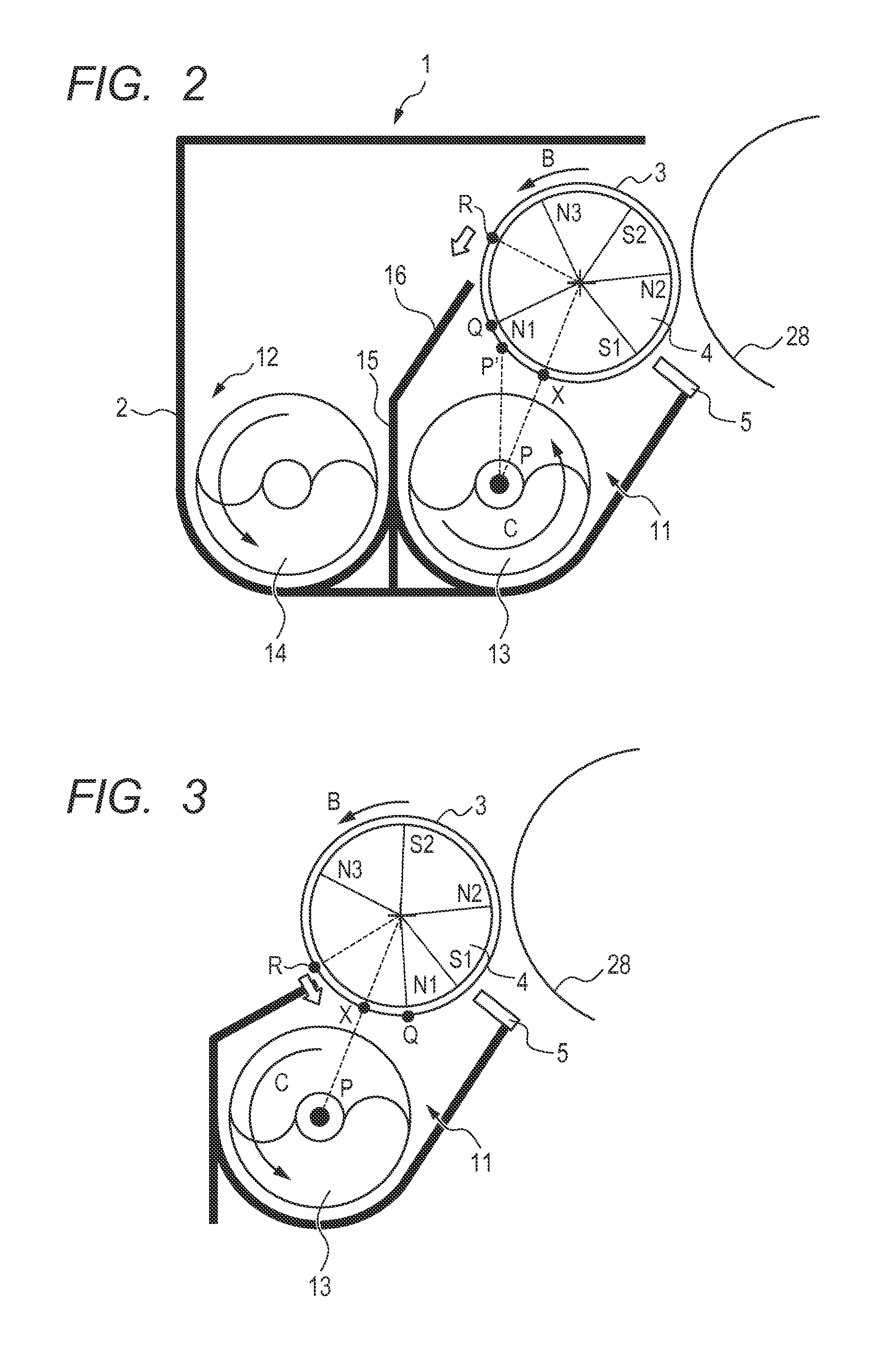
[0060]In the embodiment, as illustrated in FIG. 2, on the surface of the developing sleeve 3, the scooping position Q is arranged on the upstream side in the rotation direction B of the developing sleeve 3 with respect to a position P′ vertically above the rotation center P of the first screw 13. Specifically, the scooping position Q is arranged on the upstream side in the rotation direction B of the developing sleeve 3 with respect to the position (intersection) P′ at which a vertical line passing through the rotation center P of the first screw 13 intersects with a lower surface of the developing sleeve 3. With this, the developer can be more...
third embodiment
Local Minimum Position R of Magnetic Flux Density Br in Non-Magnetic Region
[0064]In the embodiment, as illustrated in FIG. 2, in the non-magnetic region formed between a pair of magnetic poles, a local minimum position R at which the component Br of the magnetic flux density in the normal direction with respect to the developing sleeve 3 reaches a local minimum is optimized. With this, the developer is suppressed from trailing along the developing sleeve 3. Specifically, the local minimum position R of the component Br of the magnetic flux density in the normal direction in the non-magnetic region is arranged above the rotation center of the developing sleeve 3. Thus, the developer stripped off from the developing sleeve 3 can be smoothly guided into the agitating chamber 12. Now, this configuration will be described in detail.
[0065]In the embodiment, as illustrated in FIG. 2, the guide member 16 on the partition wall 15 is close to the developing sleeve 3 near the non-magnetic regi...
PUM
 Abstract
Description
Claims
Application Information
 - R&D
- Intellectual Property
- Life Sciences
- Materials
- Tech Scout
- Unparalleled Data Quality
- Higher Quality Content
- 60% Fewer Hallucinations
Browse by: Latest US Patents, China's latest patents, Technical Efficacy Thesaurus, Application Domain, Technology Topic, Popular Technical Reports.
© 2025 PatSnap. All rights reserved.Legal|Privacy policy|Modern Slavery Act Transparency Statement|Sitemap|About US| Contact US: help@patsnap.com


