
Plasma processing apparatus and sample stage

a technology of processing apparatus and sample stage, which is applied in the direction of superimposed coating process, molten spray coating, coating, etc., can solve the problems of increasing the heat capacity of the ceramic member, the distance between the heater and the wafer becomes larger, and it is difficult to directly measure the temperature of the wafer with high accuracy, so as to improve the uniformity of the temperature of the wafer, improve the uniformity of the wafer, and improve the accuracy of the distribution

Active Publication Date: 2015-10-06
HITACHI HIGH-TECH CORP
View PDF6 Cites 7 Cited by
  • Summary
  • Abstract
  • Description
  • Claims
  • Application Information

AI Technical Summary

Benefits of technology

[0005]In the sample stage of the prior art, to improve precision in the distribution of temperature of the wafer suitable for the processing and to improve uniformity of the wafer temperature, the heater arranged in the disk-shaped ceramic member in the surface of the sample stage is subdivided into a plurality of areas. The quantity of heat generated by the heater is adjusted such that the temperature of the surface of the ceramic member is set or controlled to a desired value for each of the areas. Additionally, in each of the subdivided areas in which a plurality of heaters are disposed, to keep uniformity in the quantity of heat generated by the associated heater and to improve uniformity in the temperature in the surface direction of the wafer, the ceramic member is increased in its thickness. This increases heat capacity thereof to provide heat uniformalizing effect to reduce difference or variation in the temperature. Also, in the disk-shaped ceramic member, a plate-shaped member made of a material having high heat conductivity, for example, a metallic material is disposed to increase quantity of heat transferred through the ceramic member. This reduces the temperature variation on the surface of the ceramic member to thereby improve uniformity of the wafer temperature.
[0007]However, by increasing the thickness of the disk-shaped ceramic member and by installing the heat uniformalizing plate in the ceramic member, the distance between the heater and the wafer becomes larger. This increases heat capacity of the ceramic member, the heat capacity affecting the operation to change the temperature by the heater. Hence, even if the quantity of heat generated by the heater is adjusted to change the temperature of each film to an appropriate temperature during the wafer process, the response time from when the heat quantity is adjusted to when the adjustment reflects in the temperature of the ceramic member surface or the wafer temperature becomes longer. This leads to a fear that the difference between the appropriate temperature and an actual wafer surface temperature becomes greater during the wafer process. Hence, when it is desired to continuously process a section ranging from a hard mask to a metallic layer, precision of the wafer process is lowered. For example, the CD (critical dimension) of the metallic layer becomes thinner. Also, according to the prior art, consideration has not been fully given to a problem in which thermal resistance becomes higher between the temperature sensor disposed in the sample stage and the wafer placed thereon and the temperature difference between the temperature from the temperature sensor in the sample stage and the actual wafer temperature becomes larger. This resultantly lowers the precision in the wafer temperature adjustment.
[0008]It is therefore an object of the present invention to provide a plasma processing apparatus and a sample stage wherein the temperature adjustment precision is improved by changing the wafer temperature at a higher rate or in a shorter period of time to thereby improve wafer processing efficiency.

Problems solved by technology

However, it is difficult to directly measure the wafer temperature with high accuracy.
However, by increasing the thickness of the disk-shaped ceramic member and by installing the heat uniformalizing plate in the ceramic member, the distance between the heater and the wafer becomes larger.
This increases heat capacity of the ceramic member, the heat capacity affecting the operation to change the temperature by the heater.
This leads to a fear that the difference between the appropriate temperature and an actual wafer surface temperature becomes greater during the wafer process.
Also, according to the prior art, consideration has not been fully given to a problem in which thermal resistance becomes higher between the temperature sensor disposed in the sample stage and the wafer placed thereon and the temperature difference between the temperature from the temperature sensor in the sample stage and the actual wafer temperature becomes larger.
This resultantly lowers the precision in the wafer temperature adjustment.

Method used


Image

  • Plasma processing apparatus and sample stage
  • Plasma processing apparatus and sample stage
  • Plasma processing apparatus and sample stage

Examples


Embodiment Construction

[0019]Referring now to the drawings, description will be given of an embodiment according to the present invention.

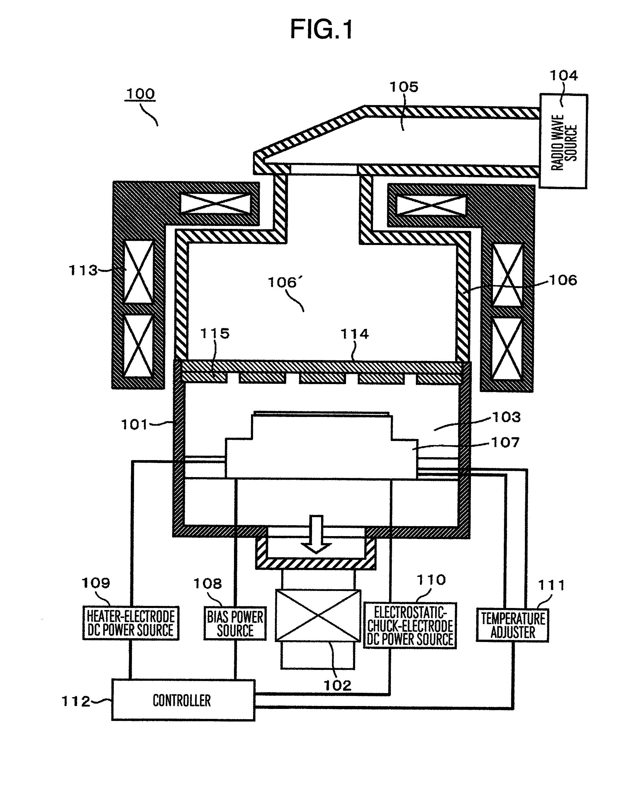
[0020]FIG. 1 is a view of a longitudinal section to explain an outline of a configuration of a plasma processing apparatus according to the present invention. The plasma processing apparatus 100 shown in FIG. 1 includes a vacuum vessel 101, an electromagnetic field supply unit disposed at a position over the vacuum vessel 101, the position being in an outer periphery thereof, to supply an electric field or a magnetic field to the vacuum vessel 101, and an exhaust unit disposed below the vacuum vessel 101 to exhaust gases therefrom.

[0021]In the vacuum vessel 101, there are arranged a processing chamber 103 in which plasma is generated and a sample as a processing object is processed by the plasma and a sample stage 107 having a surface on which the sample is placed and is held. Over the vacuum vessel 101, there are arranged a radio wave source 104, for example, a magnetr...


PUM

PropertyMeasurementUnit
thicknessaaaaaaaaaa
thicknessaaaaaaaaaa
thicknessaaaaaaaaaa

Abstract

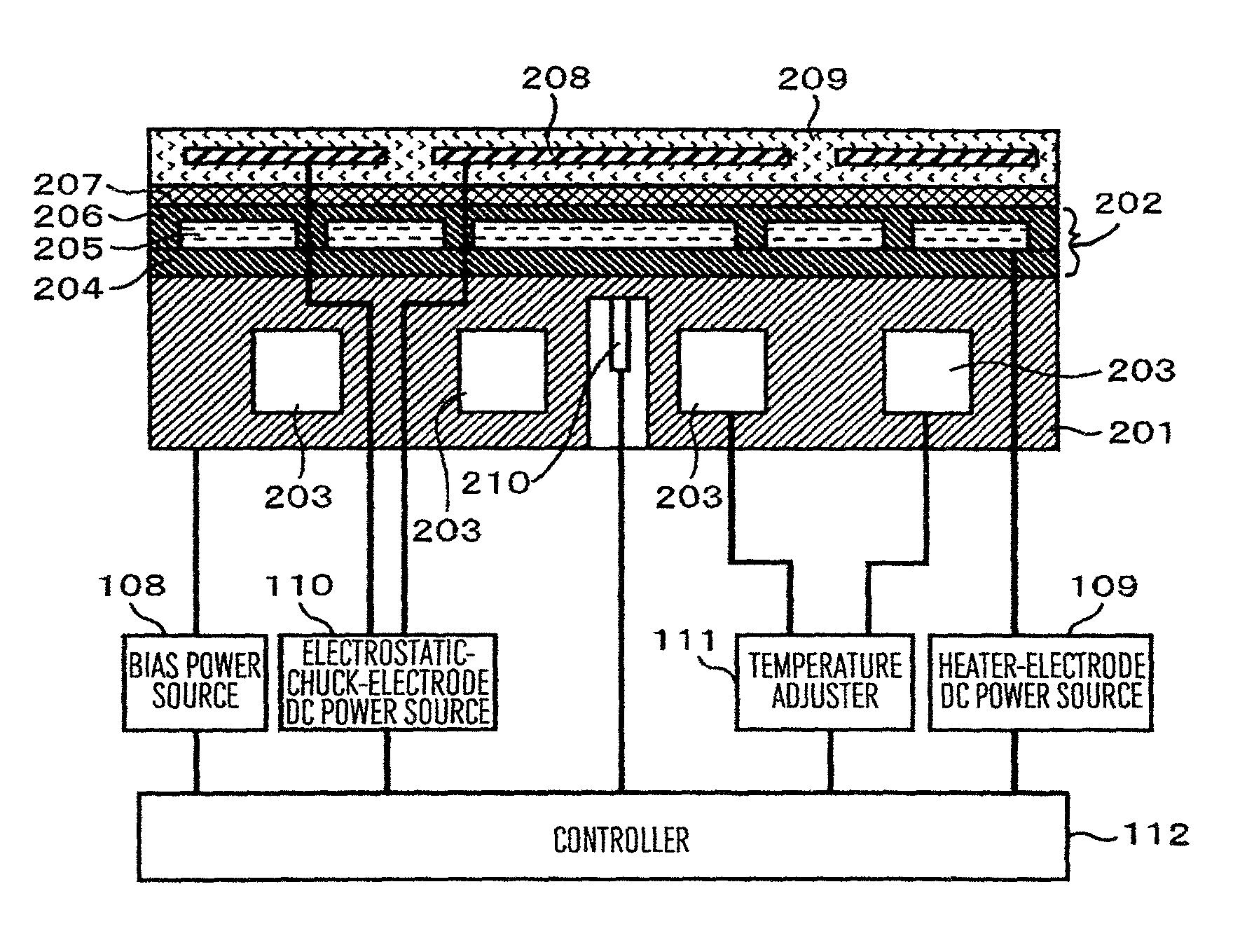
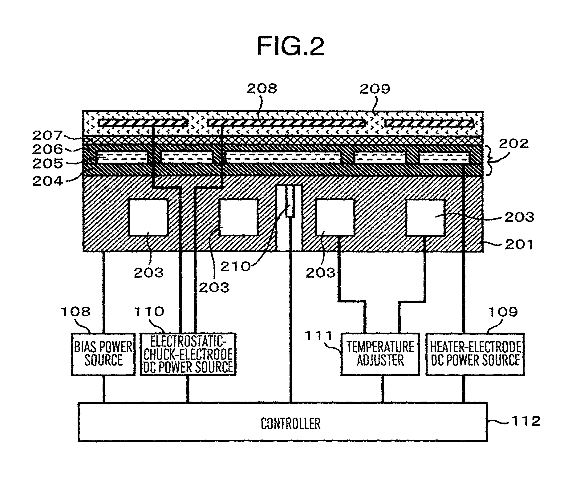
A plasma processing apparatus includes a metallic basic material arranged in a sample stage, a dielectric film of dielectric material disposed on an upper surface of the basic material, the dielectric film being formed through a plasma spray process; a film-shaped heater disposed in the dielectric film, the heater being formed through a plasma spray process; an adhesive layer arranged on the dielectric film; a sintered ceramic plate having a thickness ranging from about 0.2 mm to about 0.4 mm, the sintered ceramic plate being adhered onto the dielectric film by the adhesive layer; a sensor disposed in the basic material for sensing a temperature; and a controller for receiving an output from the sensor and adjusting quantity of heat generated by the heater.

Description

BACKGROUND OF THE INVENTION[0001]The present invention relates to a plasma processing apparatus for processing a wafer placed in a processing chamber in a vacuum vessel by use of plasma generated in the processing chamber, and in particular, to a plasma processing apparatus in which the wafer is processed while adjusting temperature of a sample stage disposed in the processing chamber to thereby adjust temperature of the wafer suitable for the processing.[0002]Such plasma processing apparatus processes a so-called multilayered film including a plurality of films which are objects of the processing and which are formed in a surface of a sample having a contour of a substrate, for example, a semiconductor wafer. To minimize the period of time required to process the multilayered film, it has been considered to process films vertically adjacent to each other of the wafer in the same processing chamber without moving the wafer to the outside of the processing chamber between the process...

Claims


Application Information

Patent Timeline
Patent Type & Authority Patents(United States)
IPC IPC(8): C23C4/00C23C28/00C23C4/02
CPCC23C28/00C23C4/02
Inventor WATANABE, TOMOYUKIYAKUSHIJI, MAMORUOHMOTO, YUTAKA
Owner HITACHI HIGH-TECH CORP
Learn More