
Cladding element

a technology of cladding and elements, applied in the field of building elements, can solve the problems of flushing mortar joints, high skill level, high cost and time consumption of masonry construction, etc., and achieve the effect of reducing dirt and debris accumulation, improving shadow zone contrast, and reducing labor intensity

Active Publication Date: 2015-09-22
JAMES HARDIE TECH LTD
View PDF17 Cites 20 Cited by
  • Summary
  • Abstract
  • Description
  • Claims
  • Application Information

AI Technical Summary

Benefits of technology

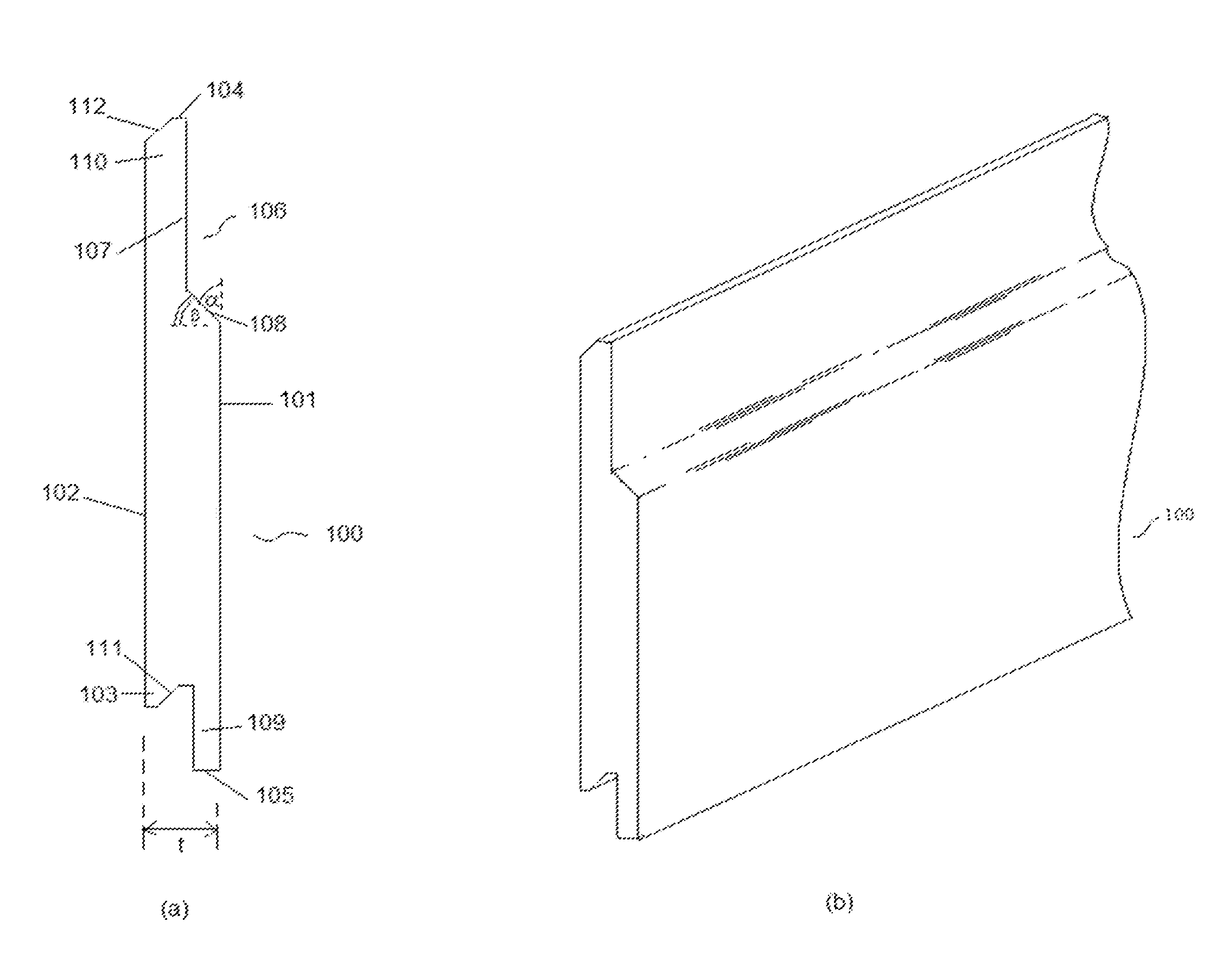
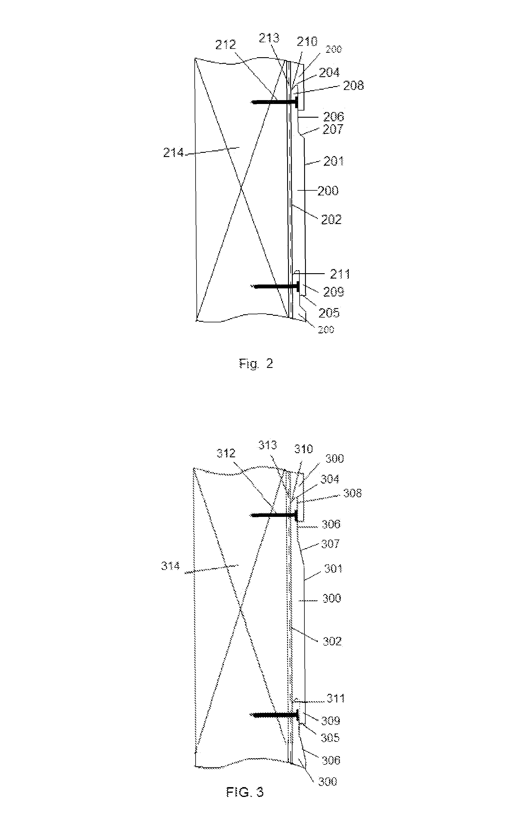
[0015]It is to be understood that the first face of the cladding element is the outer face of the cladding element. The outer face is the face of the cladding element normally in view when the cladding element is used as part of a building envelope. The advantage of the present invention is that it provides a cladding element having a profiled portion which simulates a masonry joint whilst also minimising dirt and debris accumulation on the profiled portion of each cladding element. In the preferred embodiment of the invention the profiled portion is shaped to simulate a masonry weather joint. It is of course understood that the profiled portion of the cladding element is not limited to simulate a masonry weather joint and that other types of masonry joints are also possible. The present invention also provides a cladding element comprising an improved shadow zone for contrast detail. A further advantage of the present invention is that the degree by which the angled portion is angled relative to the first face is selected to achieve a self-cleaning functionality whereby the angle is selected to aid removal using natural environmental conditions.
[0016]Accordingly, the present invention provides a cladding element suitable for simulating a masonry weather joint aesthetic, providing an improved shadow zone contrast and for minimising dirt and debris accumulation on the profiled portion of each cladding element through a self-cleaning functionality.
[0017]It is acknowledged that the term ‘comprise’ may, under varying jurisdictions be provided with either an exclusive or inclusive meaning. For the purpose of this specification, the term comprise shall have an inclusive meaning that it should be taken to mean an inclusion of not only the listed components it directly references, but also other non-specified components. Accordingly, the term “comprise” is to be attributed with as broad an interpretation as possible within any given jurisdiction and this rationale should also be used when the terms ‘comprised’ and / or ‘comprising’ are used.
[0018]In one embodiment of the invention the acute angle relative to the axes of intersection between the first face and a plane that extends perpendicularly from the first face defines an angle that is less than 90 degrees relative to two reference axes commonly known as the x- and y-axes. For the purpose of this description it is understood that the plane extending perpendicularly from the first face corresponds to the x-axis. Accordingly, it is understood that the first face corresponds to the y-axis. It is also to be understood that the first face could also correspond to the x-axis. In this circumstance, the plane that extends perpendicularly from the first face then corresponds to the y-axis.
[0019]In another embodiment of the invention, the acute angle is between 20 to 75 degrees.
[0020]In a further embodiment of the invention, the acute angle is between 30 to 60 degrees.

Problems solved by technology

Masonry construction is expensive and time consuming and requires a high level of skill to install adequately and provide durable and aesthetically acceptable joint finishing.
Flush mortar joints, however, are susceptible to water permeation and are not commonly used.
Weather joints, however, are generally overshadowed and can't provide maximum contrast between the masonry units and the mortar joints.
Dirt or debris can accumulate in the contours on the face of such profiled planks.
Such debris is difficult to remove once accumulated.
None of these provide a shadow zone or a contrast between a shadow zone and a profiled section.

Method used


Image

  • Cladding element
  • Cladding element
  • Cladding element

Examples


Embodiment Construction

[0039]Although making and using various embodiments are discussed in detail below, it should be appreciated that the invention described provides inventive concepts that may be embodied in a variety of contexts. The embodiments discussed herein are merely illustrative of ways to make and use the described invention and do not limit the scope of the invention.

[0040]In the description which follows like parts may be marked throughout the specification and drawing with the same reference numerals, respectively. The drawing figures are not necessarily to scale and certain features may be shown exaggerated in scale or in somewhat generalized or schematic form in the interest of clarity and conciseness.

[0041]Unless the context clearly requires otherwise, throughout the description and the claims, the words “inclined surface”, “angle of inclination”, and the like are to be construed as referring to inclination with respect to the plane that extends perpendicularly from the first face. In t...


PUM


Abstract

A cladding element (100), for use in a building envelope, comprising a first face (101), a second face (102) and a peripheral edge member, the first face and second face being spaced apart to define an intermediate portion of predetermined thickness (t), the peripheral edge member extending around the intermediate portion. The first face (101) comprises a profiled portion (106) simulating a masonry weather joint aesthetic thereby minimizing dirt and debris accumulation on the profiled portion of each cladding element in a constructed wall section. In addition the profiled portion provides a self-cleaning functionality. The profiled portion also provides an improved shadow zone contrast when arranged in a building array.

Description

FIELD OF THE INVENTION[0001]The present invention relates to a building element suitable for use in construction. In particular the present invention relates to a cladding element suitable for use in a building envelope.[0002]The invention has been developed primarily for use as a cladding element and will be described hereinafter with reference to this application. However, it will be appreciated that the invention is not limited to this particular field of use and that the invention can be used in any suitable field of use known to the person skilled in the art.BACKGROUND OF THE INVENTION[0003]Any discussion of the prior art throughout the specification should in no way be considered as an admission that such prior art is widely known or forms part of the common general knowledge in the field.[0004]Masonry construction is expensive and time consuming and requires a high level of skill to install adequately and provide durable and aesthetically acceptable joint finishing. It is kno...

Claims


Application Information

Patent Timeline
Patent Type & Authority Patents(United States)
IPC IPC(8): E04B2/00E04F13/076E04B5/00E04B9/00E04F13/16E04F13/08
CPCE04F13/076E04F13/0817E04F13/0864E04F13/0894E04F13/16E04F13/0801E04F2201/0107E04F13/0803E04F13/0823E04F13/0826E04F13/10
Inventor SOUTHWELL, DARREN
Owner JAMES HARDIE TECH LTD
Learn More