
Micro-electro-mechanical systems (MEMS) and corresponding manufacturing process

a technology of micro-electromechanical systems and manufacturing processes, applied in the direction of transportation and packaging, printed circuit non-printed electric components association, laboratory glassware, etc., to achieve the effect of simple and accurate way, easy and simple electric connection, and easy and simple size differences

Active Publication Date: 2015-09-15
STMICROELECTRONICS SRL
View PDF14 Cites 4 Cited by
  • Summary
  • Abstract
  • Description
  • Claims
  • Application Information

AI Technical Summary

Benefits of technology

The patent describes a technology that allows for the accurate and simple creation of ducts and passages in a printed circuit board to connect a MEMS device with external apparatus. The printed circuit board also makes it easy to make electrical connections between the MEMS device and external circuits. This technology can be adapted to different design requirements and allows for different size requirements of the external apparatus.

Problems solved by technology

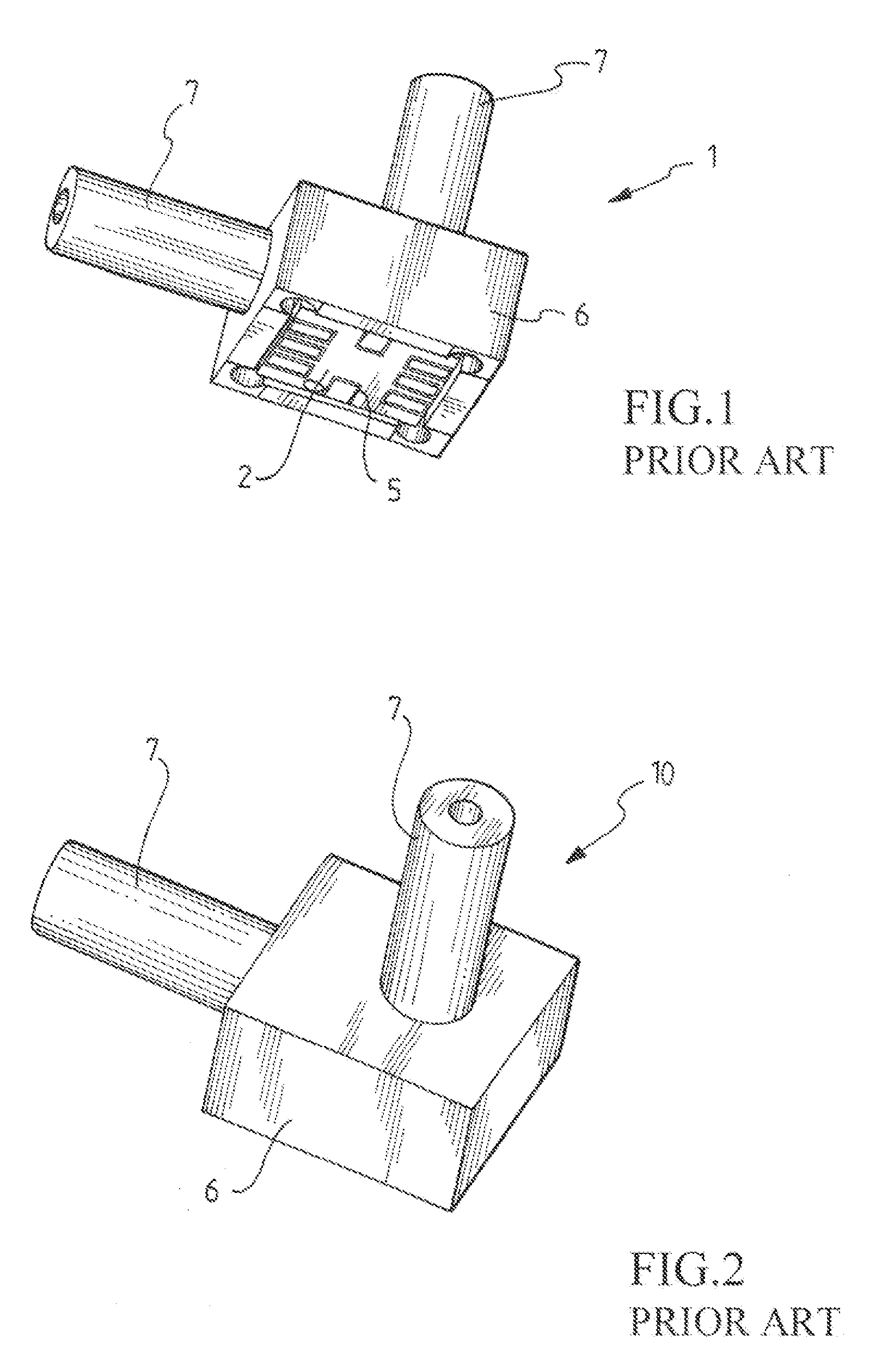
However, before being associated with the substrate 2, the MEMS device 3 is sandwich-wise interposed between two silicon dies assembled by using a glass-based material and by using a particularly difficult and critical process.

Method used


Image

  • Micro-electro-mechanical systems (MEMS) and corresponding manufacturing process
  • Micro-electro-mechanical systems (MEMS) and corresponding manufacturing process
  • Micro-electro-mechanical systems (MEMS) and corresponding manufacturing process

Examples


Embodiment Construction

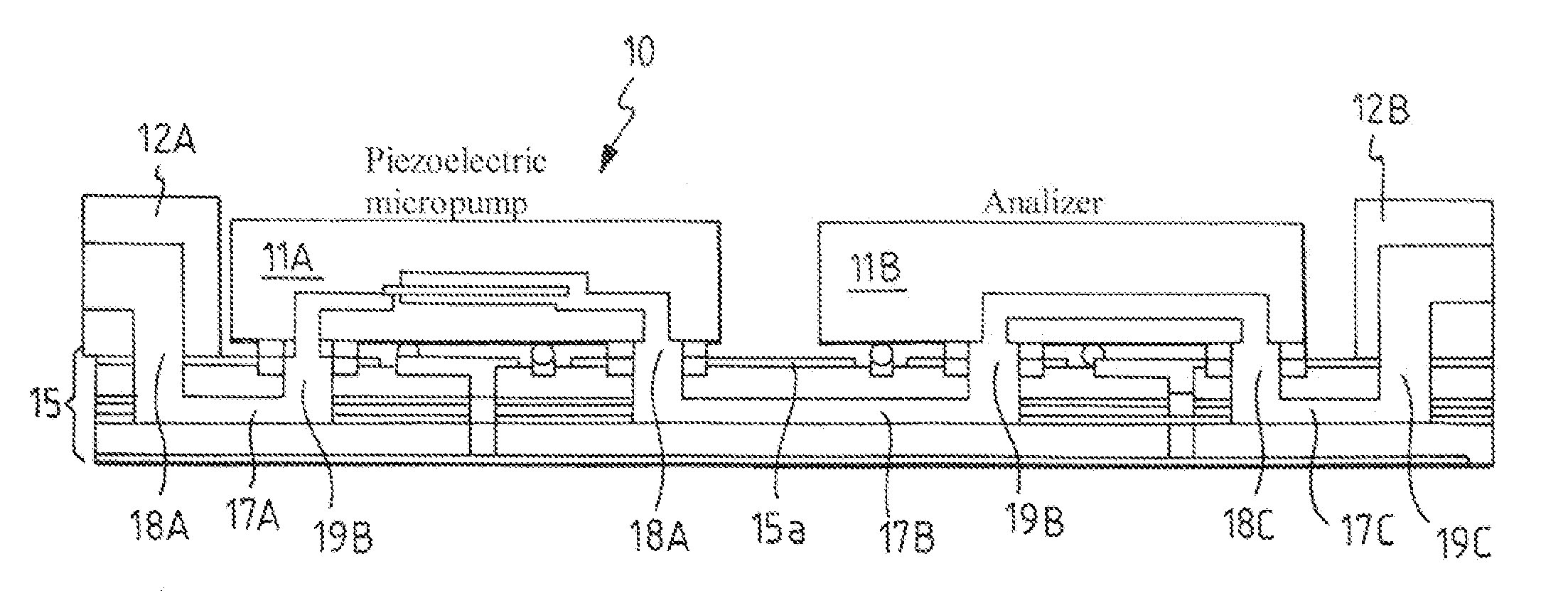
[0053]With reference to these figures, 10 globally indicates a MEMS system according to an embodiment of the present disclosure.

[0054]As shown in FIG. 7, the MEMS system 10 comprises at least one MEMS device 11 associated with a junction 15 for the connection to an external apparatus 12, such as for example a micro-tank or a fluidic pipe.

[0055]In particular, as shown in FIG. 12, the MEMS device 11 comprises a sensitive element, for example a detector 13 having a membrane, which is to be put in communication with an inlet of the external apparatus 12 to allow the flow on the detector 13 of a liquid or gaseous solution contained in the external apparatus 12.

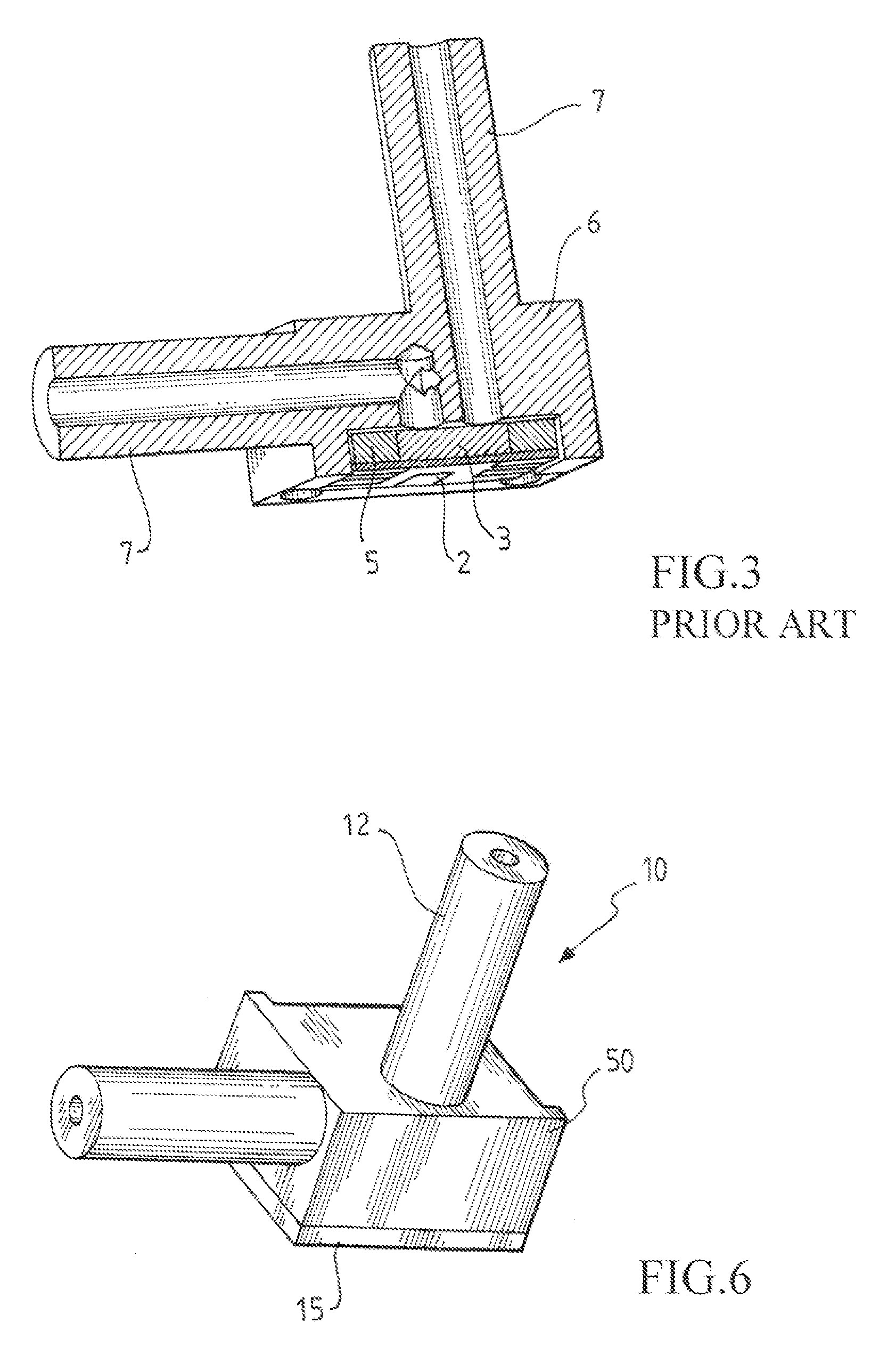
[0056]In the embodiment shown in FIGS. 6 and 7, the external apparatuses 12 are two and are respectively associated with a first and with a second detector of the MEMS device 11. Naturally, the number of external apparatuses that could be associated with the junction 15 will depend only on design requirements, as it will become app...


PUM

PropertyMeasurementUnit
conductiveaaaaaaaaaa
electricallyaaaaaaaaaa
mechanicalaaaaaaaaaa

Abstract

An embodiment of a micro-electro-mechanical system of the MEMS type comprising at least one micro-electro-mechanical device of the MEMS type and one junction with a duct suitable to being associated with an external apparatus. Said junction being a printed circuit board PCB comprising at least two layers with juxtaposed faces, a channel being present in at least one face of at least one of said at least two layers suitable for realizing the duct with the juxtaposition of the other face of at least another one of at least two layers.

Description

PRIORITY CLAIM[0001]The instant application claims priority to Italian Patent Application No. MI2008A002322, filed Dec. 24, 2008, which application is incorporated herein by reference in its entirety.TECHNICAL FIELD[0002]An embodiment of the present disclosure relates to a micro-electro-mechanical system of the MEMS type which comprises at least one MEMS device and one junction with a duct suitable to being associated with an external apparatus, such as a micro-tank and / or fluidic connection pipes.[0003]An embodiment of disclosure also relates to a process for realizing a Micro-Electro-Mechanical System of the MEMS type.BACKGROUND[0004]As it is known, MEMS is the acronym of Micro-Electro-Mechanical Systems and identifies a technology for the integration on a same substrate, in particular a die of silicon, of glass or of organic material, of devices of various nature, mechanical and / or electronic / electric, integrated in a highly miniaturized form.[0005]In particular, the MEMS technol...

Claims


Application Information

Patent Timeline
Patent Type & Authority Patents(United States)
IPC IPC(8): G01D11/24H05K3/30B01L3/00H05K1/02H05K1/18
CPCH05K1/0298B01L3/502707B01L3/502715H05K1/0272H05K3/30B01L2200/027B01L2200/12B01L2300/0816B01L2300/0887B01L2300/12H05K1/181H05K2201/10083Y10T29/4913Y10T29/49124Y10T137/0318
Inventor FONTANA, FULVIO VITTORIO
Owner STMICROELECTRONICS SRL
Learn More