
Remotely activated on-hold circuit

a technology of remote activation and on-hold circuit, which is applied in the direction of telephone line holding circuits, substation equipment, electrical apparatus, etc., can solve the problems of not giving the ability to inject music and/or messages into the hold circuit while the customer is on-hold, not compatible with all standard phones, and inconsistent methods used to place callers on-hold using these systems

Inactive Publication Date: 2015-09-15
PICA PROD DEV
View PDF1 Cites 0 Cited by
  • Summary
  • Abstract
  • Description
  • Claims
  • Application Information

AI Technical Summary

Benefits of technology

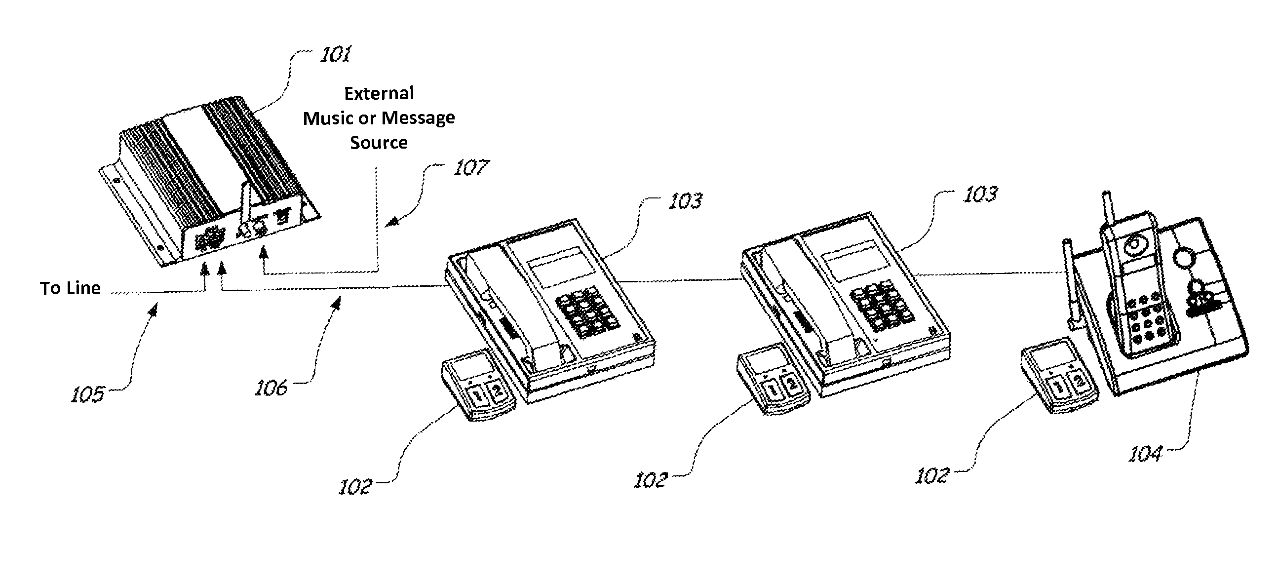
The On-Hold system is a system that allows standard telephones to have on-hold functionality without needing to modify the phone or its wiring. The system includes a central control unit that is connected between the telephone line and the phones, with wireless on-hold units associated with each phone. When a person wishes to put a phone on hold, they press a button on the wireless on-hold unit associated with their phone. This triggers a signal to be sent to the central control unit which acts on it to place the phone on hold and can also inject music or a recorded message onto the phone line towards all other phones. The system also detects when the phone is off-hole and can remove the injected message source. Additionally, the system includes a built-in LED that flashes to alert the user that a caller is in the on-hold or off-hold mode. The wireless on-hold buttons are deactivated to conserve battery when the system is not in use. Overall, the system provides convenient and easy-to-use on-hold functionality for standard telephones.

Problems solved by technology

The KSU and phones are generally for larger business and because of the cost, maintenance and complex nature of programming are not used by the small business owner.
A few problems arise when using this method since out of the complete population of single and multi-line phones that are available only a few will have a hold button.
The few phones that do incorporate a hold button generally will put the customer on-hold, but will not give the ability to inject music and / or messages into the hold circuit while the customer is on-hold.
Along with having to hardwire these devices most are not compatible with all standard phones without some type of tuning or special versions of the models that are available.
When adding additional phones after the initial installation some systems require retuning because of the additional impedance created on the phone line.
The methods used to place callers on-hold using these systems is not consistent; with some using special cumbersome buttons or large switch boxes hardwired to the phone line or phone cord.
While others utilize the touch-tone keys on the phone to activate the hold circuit which is sometime an annoyance to the customer since they hear this tone before being put on-hold.
Conventional means and methods known today for adding and implementing an “on-hold” circuit are burdensome, expensive, time-consuming, and / or do not provide a reliable method, and thus are often not deployed into service.

Method used


Image

  • Remotely activated on-hold circuit
  • Remotely activated on-hold circuit
  • Remotely activated on-hold circuit

Examples


Embodiment Construction

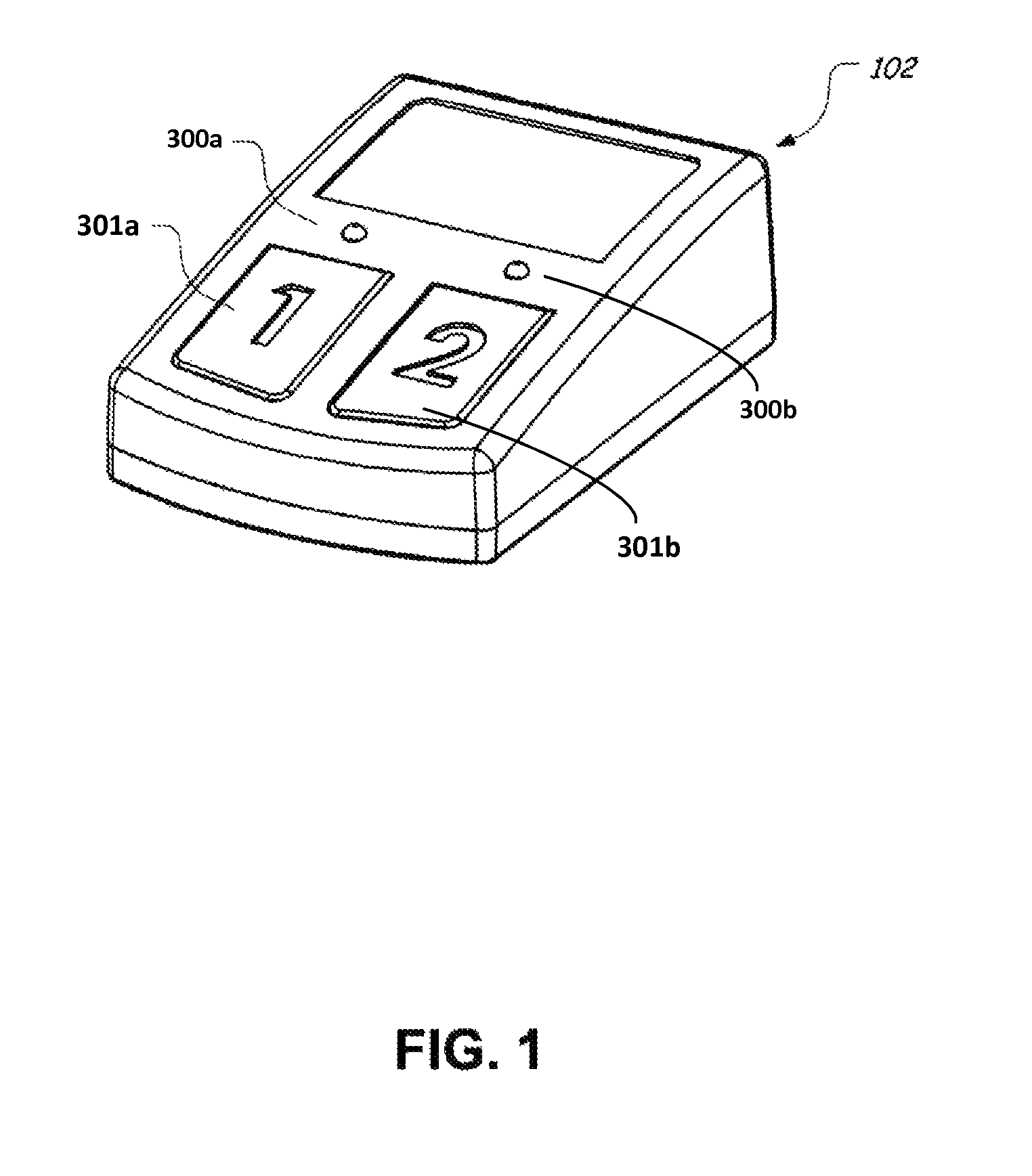
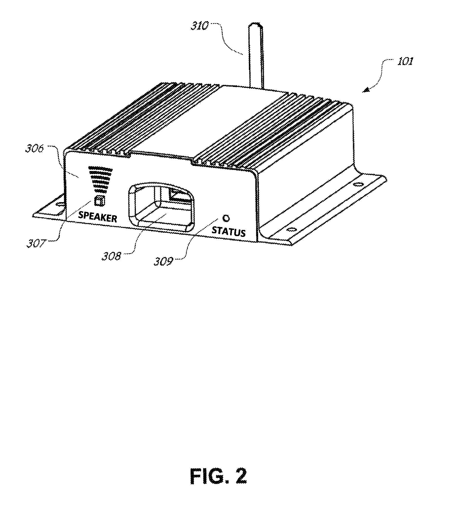
[0022]The invention basically comprises two parts, (1) a central control unit 101 (FIG. 2-front view, and FIG. 3—rear view), and (2) one or more wireless on-hold units 102 (FIGS. 1, 4). Control unit 101 is simply inserted in series between a telephone line 105 (FIG. 4) and a one or more telephone sets 103, 104 (FIG. 4) that are normally connected to the telephone line 105 via wiring 106. The telephone sets 103, 104 are standard telephone sets that have no On Hold functionality incorporated therein and the invention provides such On Hold functionality with no modifications to the telephone sets 103, 104 or their wiring.

[0023]The central control unit 101 wirelessly communicates with an On Hold unit 102 that is positioned with each telephone set 103, 104 to which on hold functionality is to be added (FIG. 4). When a person utilizing one of telephone sets 103, 104 wishes to place a current call “on hold” they depress a button 301a (one line) or 301b (two line) on the wireless On Hold un...


PUM


Abstract

A system for adding wireless on-hold capability to standard single or multi-line telephones connected to one or more phone lines. The system includes a wireless on-hold unit with transceiver associated with each telephone and each on-hold unit includes a button for each telephone line for indicating when a telephone line is to be placed into or removed from an on-hold state and a visual indicator indicating which state each telephone line is in. The system also includes a central control unit with transceiver hard wired connected between the phone lines and the telephone(s) connected to each phone line, and the central control unit places a phone line in an on-hold state or removes the on-hold state based on signals wirelessly received from the on-hold units.

Description

REFERENCE TO RELATED APPLICATIONS[0001]This application is a continuation of U.S. application Ser. No. 12 / 576,256 filed Oct. 9, 2009; the content of each of which is incorporated herein by reference in their entireties.FIELD OF THE INVENTION[0002]Embodiments of this invention generally relate to adding the capability of “on-hold” via a wireless link to standard single or multi-line phones that do not utilize a “KSU” (Key Service Unit) to activate the “on-hold” feature set. Additionally this wireless link method will allow for injection of music and messages into the phone system for a true full functioning “on-hold” circuit.BACKGROUND OF THE INVENTION[0003]There have been three main methods for adding an “on-hold” circuit to present day telephones; the first method utilizes a KSU or Key Service Unit in which the phones are specially designed to work with this main processing unit. The “on-hold” button is designed into the phones and is activated by pressing this button which in turn...

Claims


Application Information

Patent Timeline
Patent Type & Authority Patents(United States)
IPC IPC(8): H04M11/00H04M1/80
CPCH04M1/80H04M1/72513H04M1/0289
Inventor STAPLEFORD, SCOTT HOLMESSTAPLEFORD, GARY NELSON
Owner PICA PROD DEV
Learn More