
Washing machine and control method thereof

a technology of washing machine and control method, which is applied in the direction of washing machine with receptacles, lighting and heating apparatus, furnaces, etc., can solve the problems of generating vibration, limited dimension of drum type washing machine, and limited ability to change internal structure, so as to improve the support structure, increase the capacity of the tub, and achieve effective capacity-increasing

Inactive Publication Date: 2015-09-15
LG ELECTRONICS INC
View PDF25 Cites 20 Cited by
  • Summary
  • Abstract
  • Description
  • Claims
  • Application Information

AI Technical Summary

Benefits of technology

The present invention provides a washing machine that can increase the capacity of the tub without increasing its exterior size and improve its supporting structure. It also prevents overheating by controlling the temperature of heated-air, enhances stability, reliability, and user convenience. Furthermore, it has security by preventing breakage of an overheated door glass. Additionally, it performs natural cooling type condensation without using auxiliary forced cooling means, reduces maintenance of less water usage, and has an improved condensation rate.

Problems solved by technology

Such the drum type washing machine having the structure mentioned above generates vibration because of a rotational force of the drum generated when it is rotated and eccentricity of the laundry as an inevitable consequence.
As a result, the dimension of the drum type washing machine has to be limited by an installation environment.
It is limited to change an internal structure of such the drum type washing machine for the structure of the spring and damper provided between the tub and the cabinet to suspend and dampen the vibration, as mentioned above.
Also, it is limited to change the dimension of the washing machine, because the installation environment of the drum type washing machine is limited.
However, it is quite difficult in the structure of the conventional drum type washing machine to improve the dimension of the tub to improve the washing capacity, because of the limited conditions mentioned above.
Because of that, the conventional washing machine has a problem of failure in preventing the overheating which might be generated at a specific spot on an entire passage where air is circulated.
As a result, the possibility of the overheating generated on the heated-air passage between the heater and the drum can be growing disadvantageously.
Especially, as the heated-air is constantly supplied in an initial stage of the heated-air supply, the possibility of the overheating on the heated-air passage between the heater and the drum seems to be growing more.
Such the overheating may generate heat distortion or damage of elements.
Because of that, there may be a concern of deteriorated stability and reliability of the washing machine.
However, it is impossible to precisely sense the end timing of the drying by using the temperature of the heated-air.
Because of that, the drying is performed for a less time period that fails to reach the end timing of the drying and the laundry happens to be not dried sufficiently.
Or, the drying is performed for a more time period that passes the end timing of the drying and the laundry happens to damage accordingly.
Therefore, the conventional washing machine having the drying function may have a problem of incomplete laundry drying because of external condition change.
In this case, the user has to operate additional drying of the laundry inconveniently.
Also, it has a problem of too much drying performed for the laundry because of external condition change.
In this case, damage to the laundry might be generated by too much heated-air.

Method used


Image

  • Washing machine and control method thereof
  • Washing machine and control method thereof
  • Washing machine and control method thereof

Examples


Embodiment Construction

[0055]As follows, embodiments of the present invention will be described in detail in reference to the accompanying drawings.

[0056]The present invention relates to a washing machine having a drying function and it is not limited to a specific type washing machine. The present invention is not limited to a drum type dryer or a drum type washing machine having a drying function, which will be described later.

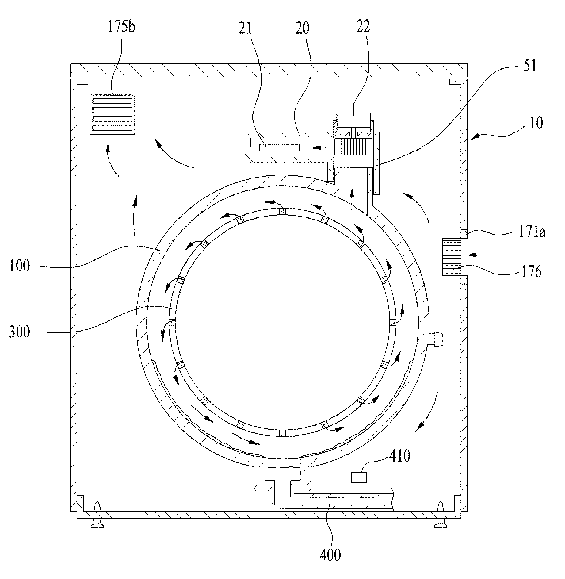
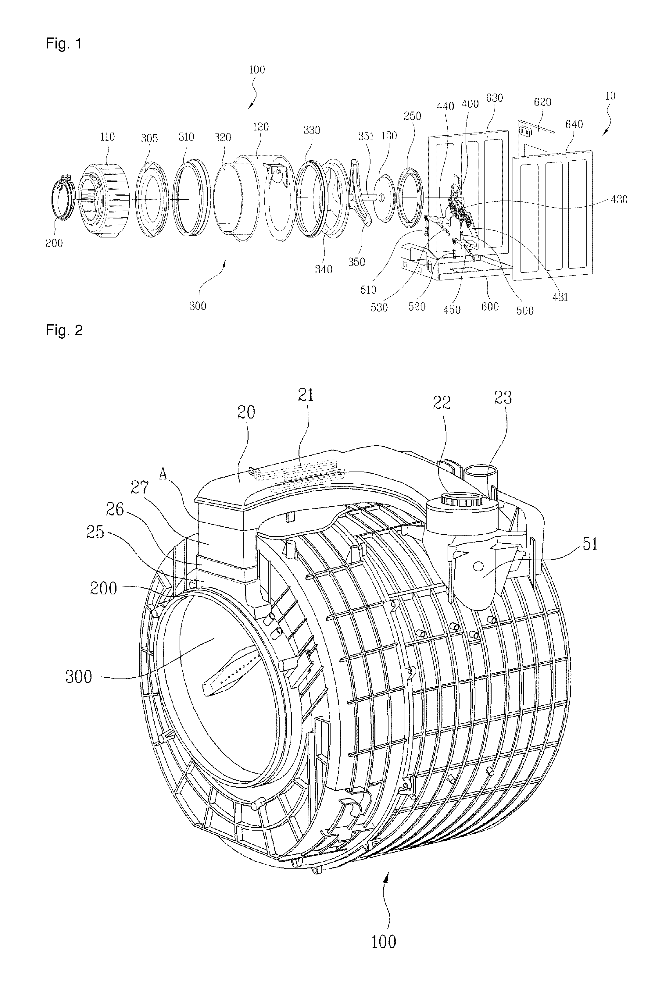
[0057]FIG. 1 illustrates a washing machine according to an embodiment. The washing machine shown in FIG. 1 is a washing machine having a drying function. This embodiment represents that a condensation part provided in the washing machine according to this embodiment is a tub.

[0058]The washing machine according to the present invention may include a tub 100 that is fixedly supported by a cabinet 10. The tub 100 may include a tub front 110 defining a front part thereof and a tub rear 120 defining a rear part thereof.

[0059]The tub front 110 and the tub rear 120 may be assembled by a ...


PUM


Abstract

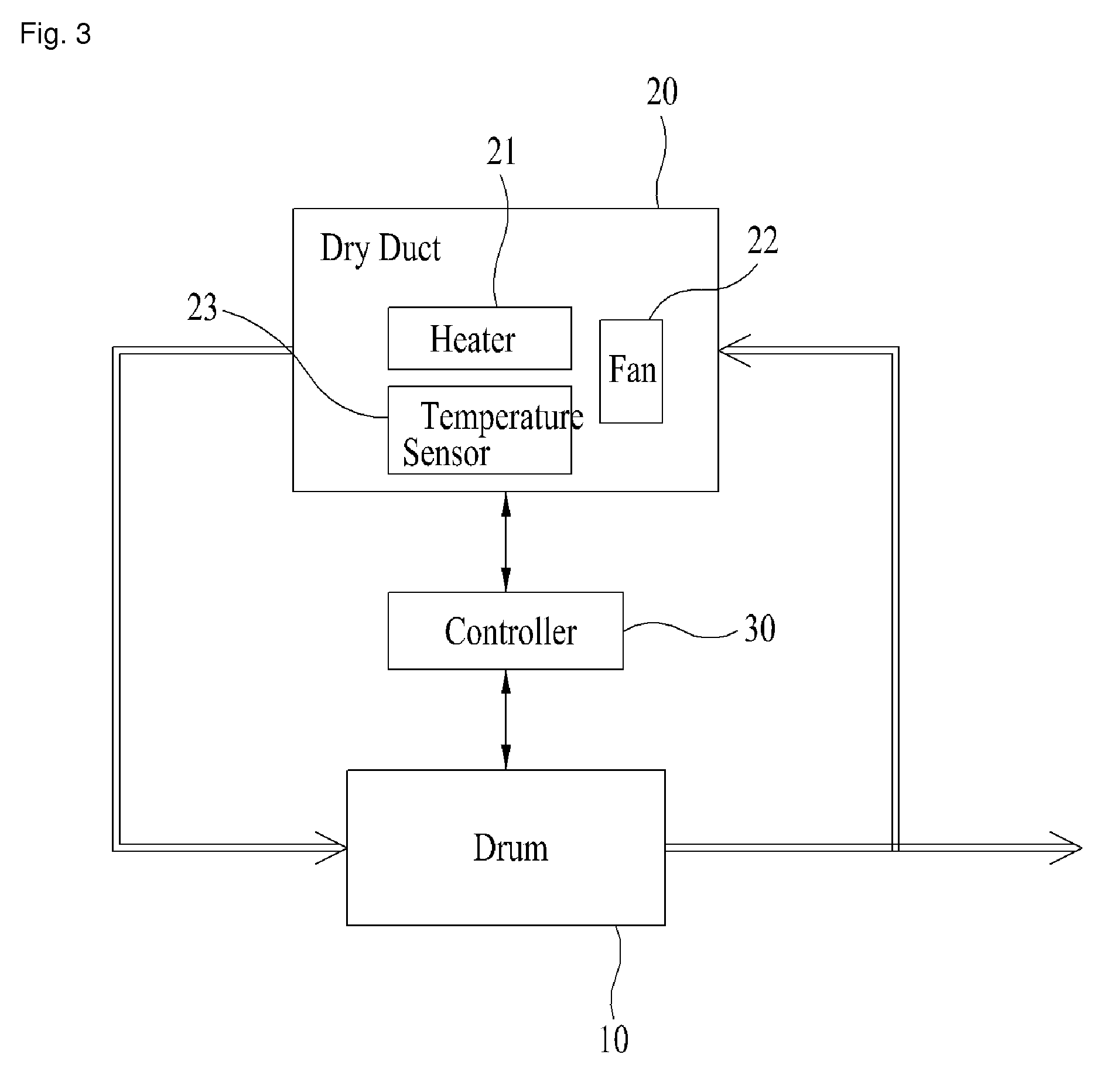
A washing machine and a control method therefore are disclosed. The washing machine includes a cabinet (10); a tub (100) fixed to the cabinet (10); a drum (300) rotatably provided in the tub (100); a dry duct (20) which heats air exhausted from the tub (100) a predetermined temperature, to re-supply the heated air to the tub (100); condensation unit (170) which condenses moisture on at least a predetermined area of an inner circumferential surface of the tub (100) by heat-exchanging external air of the cabinet (10) with at least predetermined area of an outer circumferential surface of the tub (100); and sensing unit (410) which senses the amount of condensate generated in the tub (100). A washing machine and a control method thereof are disclosed. The washing machine includes a cabinet; a tub fixed to the cabinet; a drum rotatably provided in the tub; a dry duct which heats air exhausted from the tub a predetermined temperature, to re-supply the heated air to the tub; condensation unit which condenses moisture on at least a predetermined area of an inner circumferential surface of the tub by heat-exchanging external air of the cabinet with at least predetermined area of an outer circumferential surface of the tub; and sensing unit which sense the amount of condensate generated in the tub.

Description

CROSS-REFERENCE TO RELATED PATENT APPLICATIONS[0001]This application is a U.S. National Stage Application under 35 U.S.C. §371 of PCT Application No. PCT / KR2011 / 007232, filed Sep. 30, 2011, which claims priority to Korean Patent Application No. 10-2010-0101760, filed Oct. 19, 2010.TECHNICAL FIELD[0002]The present invention relates to a washing machine and a control method thereof.BACKGROUND ART[0003]Generally, a washing machine is an electric appliance which is able to remove various contaminants attached to clothes, beddings and wearable items (hereinafter, laundry) by using emulsion action of detergent, friction of water currents generated by rotation of a pulsator or drum and shock applied to laundry. A full-automatic washing machine which is introduced recently performs a series of cycles including washing, rinsing and dry-spinning courses automatically, without a manual operation.[0004]In recent, demands for drum type washing machines have been increasing gradually, because dru...

Claims


Application Information

Patent Timeline
Patent Type & Authority Patents(United States)
IPC IPC(8): D06F58/20D06F58/24D06F33/02D06F25/00D06F58/28
CPCD06F25/00D06F33/02D06F58/24D06F58/28D06F2058/2854D06F2058/2896D06F58/38D06F2103/08D06F2103/38D06F58/04D06F2103/58D06F39/087D06F37/22D06F33/00D06F58/30D06F39/10D06F58/22D06F39/04D06F34/18D06F34/22
Inventor HONG, SANGWOOK
Owner LG ELECTRONICS INC
Learn More