Light-controlling device and method of manufacturing the same

a technology of light control and control device, which is applied in the direction of optics, instruments, optical elements, etc., can solve the problems of not being able to achieve the high light transmittance and high shielding rate at the same time, and still lacks sufficient light transmittance and/or light shielding properties in many applications

Active Publication Date: 2015-09-08
E INK CORPORATION
View PDF10 Cites 0 Cited by
  • Summary
  • Abstract
  • Description
  • Claims
  • Application Information

AI Technical Summary

Benefits of technology

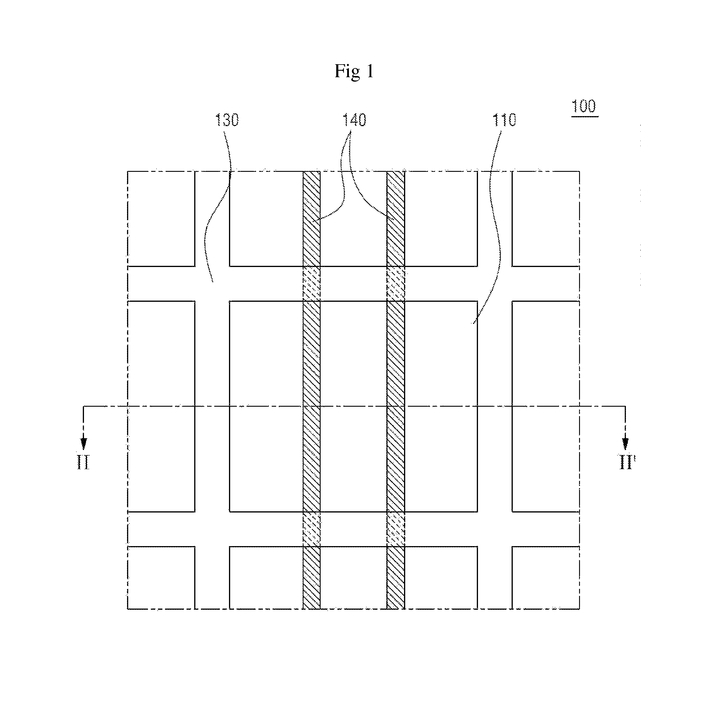
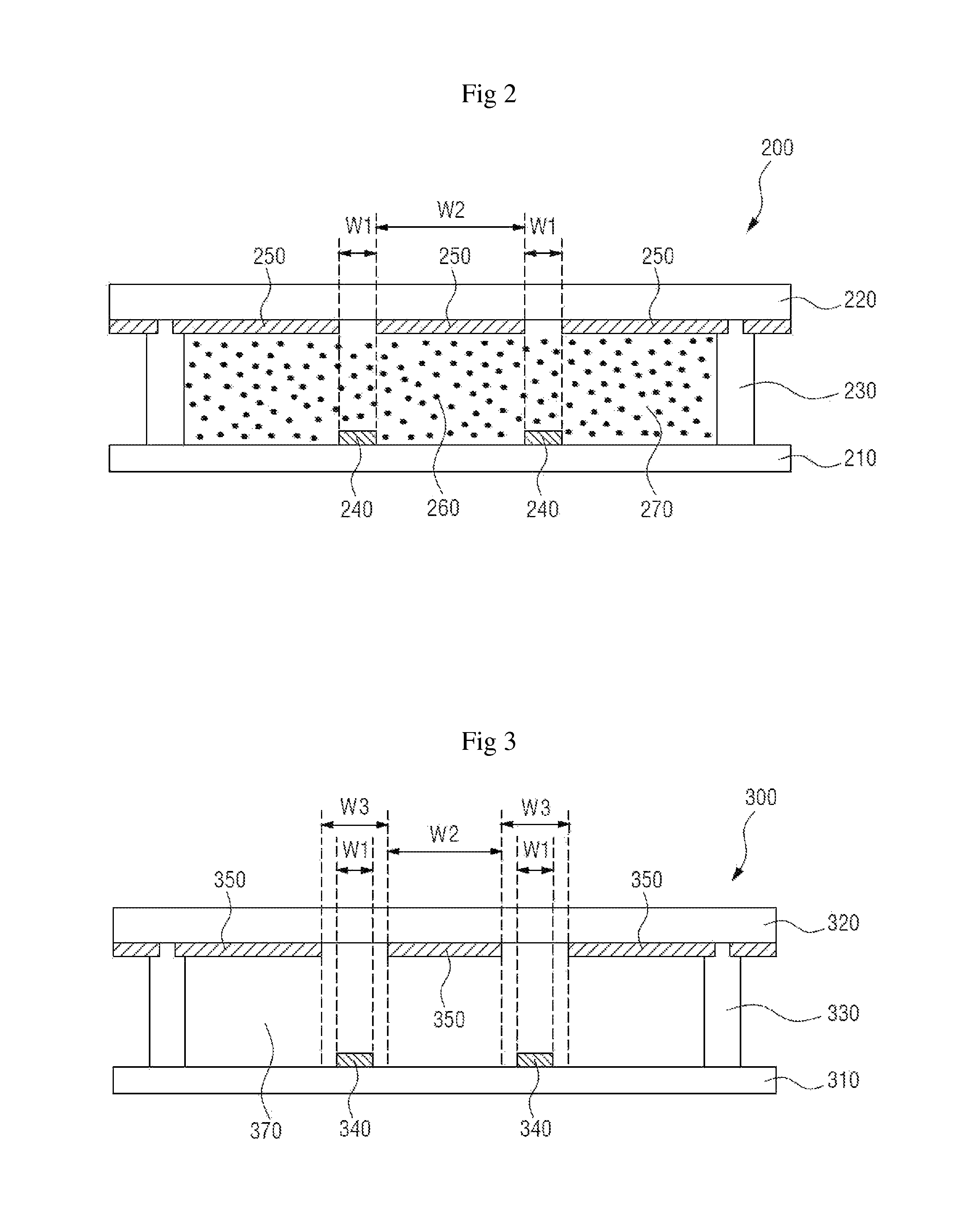
[0009]In an aspect, the present disclosure is related to an improved light-controlling. The light-controlling device includes a first substrate and a second substrate. The light-controlling device also includes a partition wall separating the first and second substrates to define a cell. Within the cell, an optical medium, which contains charged particles, is disposed therein. The light-controlling device further includes a plurality of first electrodes and a plurality of second electrodes for generating electrical field to move at least some of the charged particles within the cell. Each of the first electrodes has a first width and a first thickness, and is disposed on the first substrate within the cell. Each of the second electrodes has a second width and a second thickness, and is disposed on the second substrate within the cell. Each second electrode on the second substrate is disposed at an interval of a third width (i.e., distance between the two adjacent edges of the adjacent second electrodes). During the operation of light-controlling device, the electric field between the spreading electrodes and the collecting electrode is normalized due to the relative position of the open region and the collecting electrodes. Accordingly, the charged particles can spread more evenly on the spreading electrodes without any defects (e.g., uncovered region or unevenly covered region during the shielding mode).
[0013]In some embodiments, at least one of the first electrodes has a buckled surface with projections of a first height and recesses with a first depth so that increased number of charged particles can be adhered on the first electrode. The charged particles can have shorter diameter than the first height and the first depth to further increase the number of charged particles that can be adhered to the first electrode. For instance, each of the charged particle may have a diameter of about 5 nm to about 1 μm.
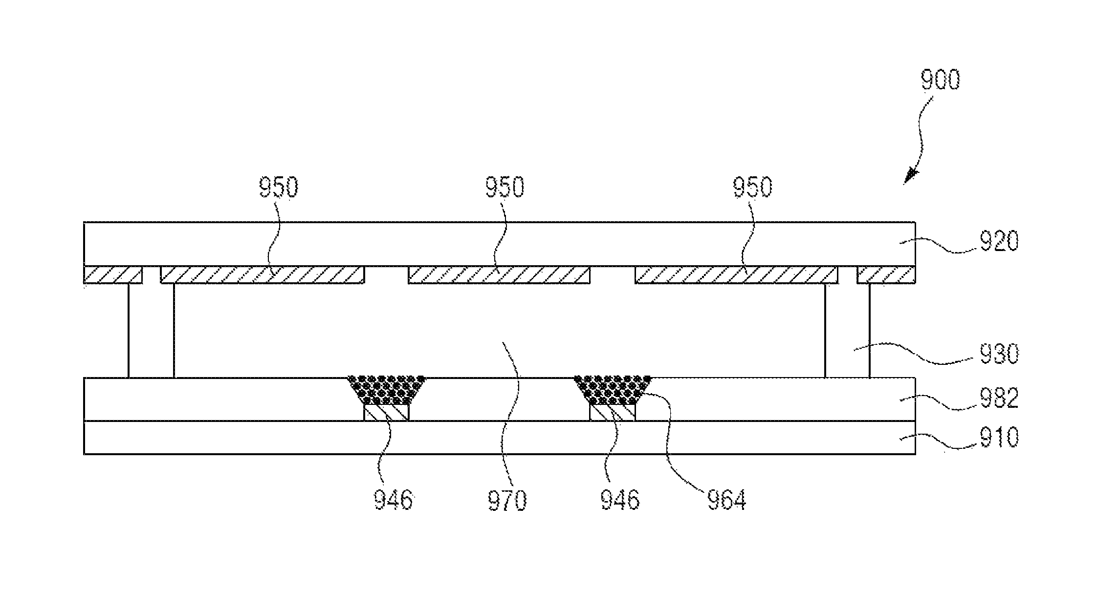
[0014]In some embodiments, the light-controlling device further includes a particle guidance member on the first substrate with opening at each of the first electrodes. The particle guidance member has a third thickness, which is greater than the first thickness of the first electrode. When the light-controlling device operates in the light transmittance mode, the particle guidance member directs, or otherwise guides, the charged particles towards the collecting electrode disposed within the hollow space. Due to the difference in the thicknesses, a hollow space is formed over the first electrode. The hollow space holds the charged particles in a limited space when the first electrode is activated to attract the charged particles. In other words, the hollow space serves as a reservoir for holding the charged particles during the light transmittance mode. Because the charged particles are stacked over within the limited width of the hollow space, more charged particles can be employed by the light-controlling device without negatively affecting the light transmittance rate.
[0016]In an aspect, the present disclosure is related to a light-controlling device. In one embodiment, a light-controlling device includes a first substrate and a second substrate. A plurality of charged particles is interposed between the first and second substrates. On one of the first and second substrates, a spreading electrode disposed thereon. Also included in the light-controlling device are one or more collecting electrodes disposed on at least one of the first and second substrates. The collecting electrode and the spreading electrode are electrically insulated from each other. The spreading electrode and the collecting electrode may be covered with an insulation layer to prevent the plurality of charged particles from directly contacting the electrodes and lose its charged state.

Problems solved by technology

These properties, however, generally have a trade-off relationship with each other, and therefore it is often difficult to achieve both the high light transmittance and the high shielding rates at the same time.
Attempts have been made by using polymer disperse liquid crystal (PDLC) having a varied light intensity, but it still lacks sufficient light transmittance and / or light shielding properties in many applications.

Method used


Image

  • Light-controlling device and method of manufacturing the same
  • Light-controlling device and method of manufacturing the same
  • Light-controlling device and method of manufacturing the same

Examples


Embodiment Construction

[0032]Exemplary embodiments of the present invention will be described in detail below with reference to the accompanying drawings. While the present invention is shown and described in connection with exemplary embodiments thereof, it will be apparent to those skilled in the art that various modifications can be made without departing from the spirit and scope of the invention. It should be understood that the dimensions of the elements shown in the drawings may have been exaggerated for easier explanation of the embodiments and are not intended to limit the scope of the present invention.

[0033]An element or layer formed “on” another element or layer includes all for a case in which an element is directly formed on another element, and for a case in which an element is formed on another element with an additional element or layer formed therebetween.

[0034]Although the terms first, second, etc. may be used to describe various elements, it should be understood that these elements are...


PUM


Abstract

A light-controlling device is provided. The light-controlling device includes a first substrate, a second substrate disposed opposite the first substrate, and a partition wall separating the first and second substrates to define a cell. An optical medium containing charged particles is disposed within the cell between the first and second substrates. A plurality of first electrodes is disposed on the first substrate, and a plurality of second electrodes is disposed on the second substrate to generate electrical field within the cell to move at least some of the charged particles. Each of the first electrodes has a first width and a first thickness, and each of the second electrodes has a second width and a second thickness. Each of the second electrodes is disposed at an interval of a third width such that the open region on the second substrate between the second electrodes corresponds to the first electrode on the first substrate.

Description

CROSS-REFERENCE TO RELATED APPLICATION[0001]This application claims priority to and the benefit of Korean Patent Application No. 2012-0144932, filed on Dec. 12, 2012, the disclosure of which is incorporated herein by reference in its entirety.BACKGROUND[0002]1. Field of the Invention[0003]The present invention relates to a light-controlling device, and more particularly, to a light-controlling device with increased light transmittance and shielding rate, and method of increasing the light transmittance and shielding rate in such a light-controlling device.[0004]2. Discussion of Related Art[0005]Research has been conducted on a light-controlling device that may be applied to windows, automobiles, airplanes, optical devices, or image display devices to control light transmittance or reflectance. The light-controlling device may block, reflect, scatter, or transmit light in an ultraviolet (UV) region, a visible light region, or a near-infrared (NIR) region due to the characteristics an...

Claims


Application Information

Patent Timeline
Patent Type & Authority Patents(United States)
IPC IPC(8): G02B26/00G02B26/02
CPCG02B26/026
Inventor LEE, MOON SUNAN, HYUNJIN
Owner E INK CORPORATION
Why Eureka
Try Eureka