
Power grid operation control system, device, and method

a technology of operation control system and power grid, applied in transmission systems, electric signal transmission systems, electric power transfer ac networks, etc., can solve problems such as power supply and demand imbalance, system frequency fluctuation, and affecting the utilization of renewable energy, so as to increase the amount of renewable energy introduction, increase the utilization factor of each renewable energy, and increase the effect of output fluctuation

Active Publication Date: 2015-09-01
HITACHI LTD +3
View PDF5 Cites 23 Cited by
  • Summary
  • Abstract
  • Description
  • Claims
  • Application Information

AI Technical Summary

Benefits of technology

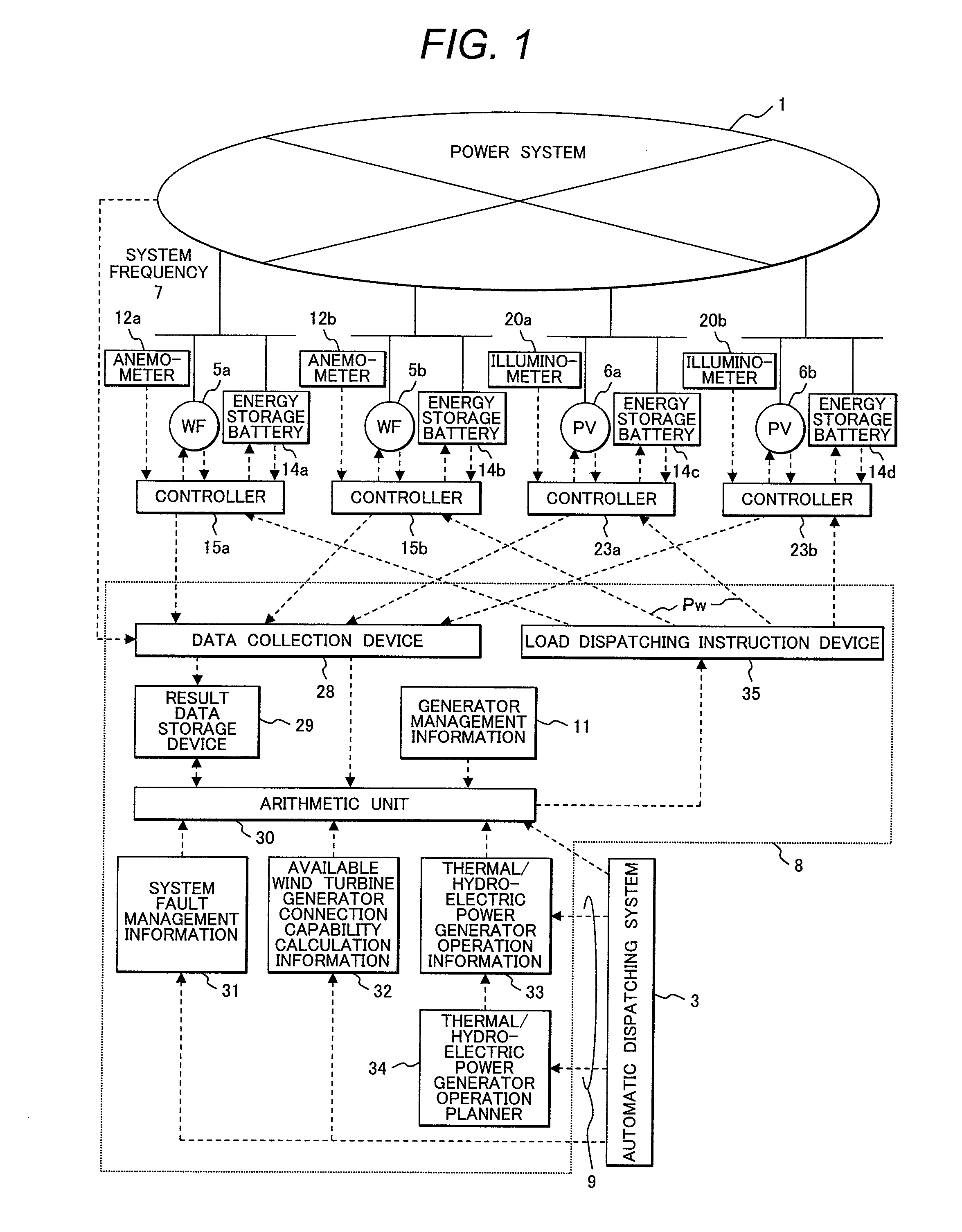
[0023]According to the above-described aspects of the present invention, the overall output fluctuation of renewable energy (e.g., wind turbine generators and photovoltaic power generation) can be effectively suppressed and controlled. This makes it possible to contribute to the correction of power supply and demand imbalance of the power grid, improve the utilization factor of each renewable energy, and increase the amount of renewable energy introduction into the power grid.

Problems solved by technology

However, when a generator based on renewable energy is used, the amount of electrical power generated by such a generator varies with solar radiation, wind conditions, and other weather conditions that are difficult to predict accurately.
This causes power supply and demand imbalance.
This imbalance causes fluctuation in system frequency, thereby incurring power quality deterioration.
However, such an energy storage battery costs too much, thereby increasing the unit cost of renewable energy system power generation.
However, when the proportion of the renewable energy based generators increases within the power grid, the capacity furnished by the existing thermal power generators and hydroelectric power generators becomes insufficient.
However, even when the method described in Japanese Patent No. 4559577 is exercised after the method described in “Normal / Emergency Load Frequency Control in Power grid” by Power grid Technical Committee of Electrical Power Energy Division of the Institute of Electrical Engineers of Japan (Technical Report of the Institute of Electrical Engineers of Japan, No. 869) is used to determine the available wind turbine generator connection capability interconnectable to the power grid, the power grid cannot be steadily operated while making the most of the renewable energy based generators.
There are various problems with the determination of the available wind turbine generator connection capability.
Further, although the available wind turbine generator connection capability is constantly changing due to the occurrence of system faults and changes in the load fluctuation of users connected to the power grid, the wind turbine generator connection capability becomes excessive or inadequate.
Furthermore, the electrical power generated by a wind turbine generator depends on weather conditions so that a time zone where the wind turbine generator can be operated at full rated capacity is extremely limited.
This makes it impossible to make effective use of the renewable energy.
For example, even if the total rated power generation capacity of a plurality of system-interconnected wind turbine generators is suppressed to 90%, which is not higher than the available wind turbine generator connection capability, the rated power generation output of the wind turbine generators cannot always be obtained due to the weather conditions.
This makes it impossible to make the most of the renewable energy.

Method used


Image

  • Power grid operation control system, device, and method
  • Power grid operation control system, device, and method
  • Power grid operation control system, device, and method

Examples


Embodiment Construction

[0030]An embodiment of the present invention will now be described.

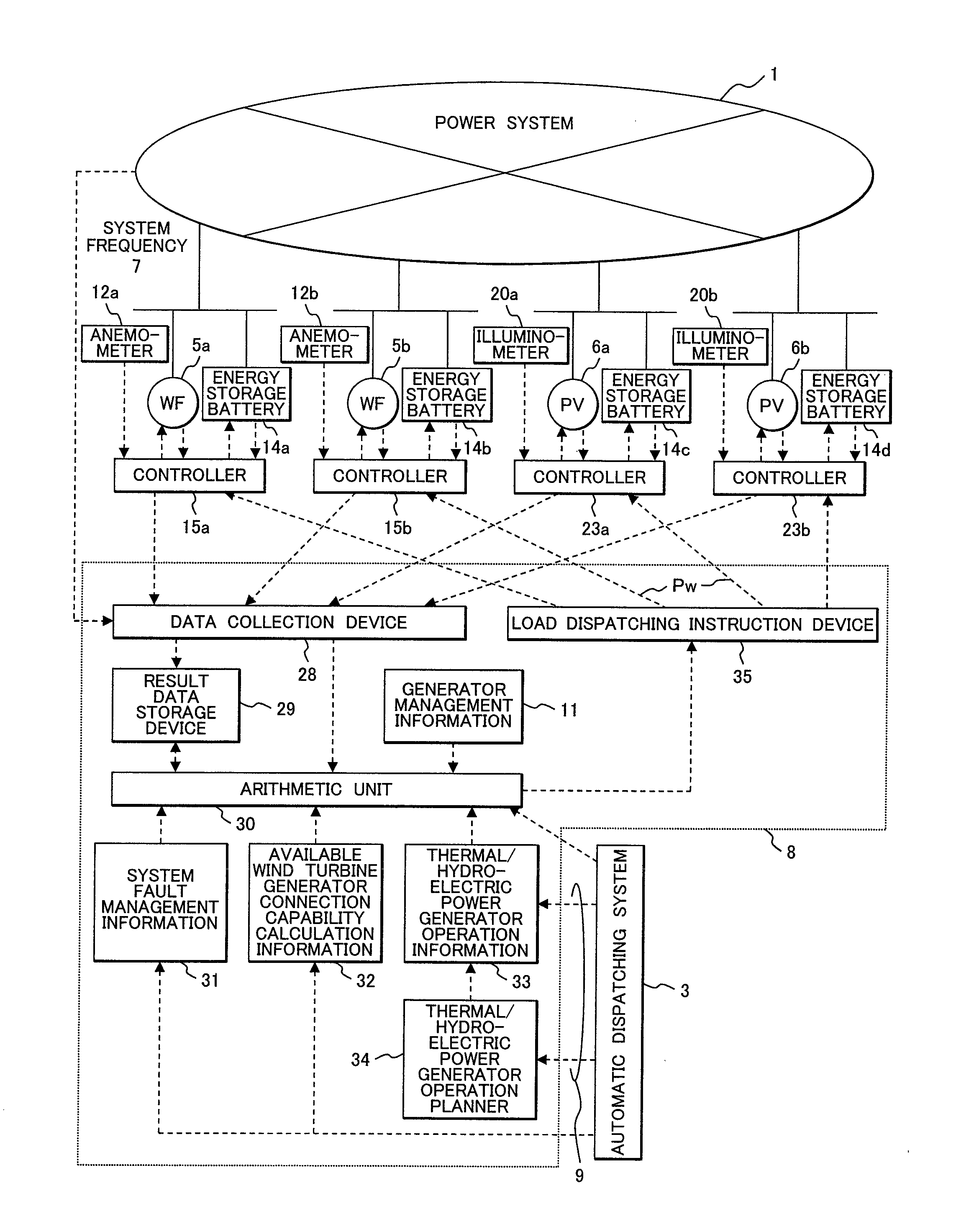
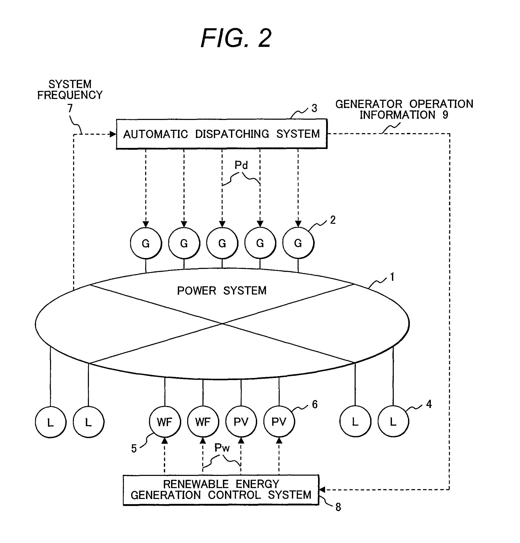
[0031]FIG. 2 shows a configuration of a power grid operation control system applied to a power grid including renewable energy. Referring to FIG. 2, the power grid 1 includes renewable energy, such as wind turbine generators 5 and photovoltaic power generation 6, in addition to existing generators 2, such as thermal, hydroelectric, or nuclear power generators, and supplies electrical power generated by the generators to loads 4 (users) through transmission lines, transformers, and the like.

[0032]To control the power grid 1, an automatic dispatching system 3 determines the difference between the demand of the loads 4 connected to the power grid 1 and the amount of electrical power generated by the existing generators 2 such as the thermal, hydroelectric, or nuclear power generators, and issues an output change instruction Pd to the existing generators 2 such as the thermal, hydroelectric, or nuclear power generators f...


PUM


Abstract

A power grid operation control system, device, and method for steadily operating a power grid while making the most of renewable energy. The power grid operation control system serves a power grid connected to a plurality of renewable energy and a plurality of thermal / hydroelectric power generators, and includes an automatic dispatching system, which controls the thermal / hydroelectric power generators, and a renewable energy generation control system, which controls the renewable energy. The automatic dispatching system controls the thermal / hydroelectric power generators by generating an automatic frequency control signal for correcting the power supply and demand imbalance of the power grid. The renewable energy generation control system determines an available connection capability and issues load instructions to ensure that the total power generation capacity of the renewable energy does not exceed the available connection capability.

Description

CLAIM OF PRIORITY[0001]The present application claims priority from Japanese Patent application serial no. 2011-142790 , filed on Jun. 28, 2011 , the content of which is hereby incorporated by reference into this application.FIELD OF THE INVENTION[0002]The present invention relates to a power grid operation control system, device, and method, and more particularly to an operation control system, device, and method for a power to which a plurality of wind turbine generators, photovoltaic power generation, or other generators based on renewable energy are connected for operation purposes.BACKGROUND OF THE INVENTION[0003]In recent years, power grids have increasingly used wind turbine generators, photovoltaic power generation, or other generators based on renewable energy. It is demanded that such power grids make effective use of electrical power generated by renewable energy.[0004]However, when a generator based on renewable energy is used, the amount of electrical power generated by...

Claims


Application Information

Patent Timeline
Patent Type & Authority Patents(United States)
IPC IPC(8): H02J3/00H02J3/38H02J3/34
CPCH02J3/382H02J3/34H02J2003/007Y02E60/76Y04S40/22Y10T307/718H02J2203/20H02J2300/20H02J3/381Y02E60/00Y04S40/20H02J2300/24H02J3/46H02J2300/28Y02E10/56
Inventor MORI, SHIGEKIGIMA, YUUTAKINJO, RYUTASHINJO, FUMIHIROUEZU, YASUNORIKAGAWA, EIICHIRO
Owner HITACHI LTD
Learn More