
Vertical take-off and landing aircraft

a vertical take-off and landing aircraft technology, applied in the field of aerial vehicles, can solve the problems of inherently unstable between the direct and redirected thrust orientation of the vtol drone, the turbofan/jet engine of the redirected thrust vtol drone is prone to overheating and failure, and the difficulty of engineering and construction

Active Publication Date: 2015-09-01
L3HARRIS UNMANNED SYST INC
View PDF18 Cites 183 Cited by
  • Summary
  • Abstract
  • Description
  • Claims
  • Application Information

AI Technical Summary

Benefits of technology

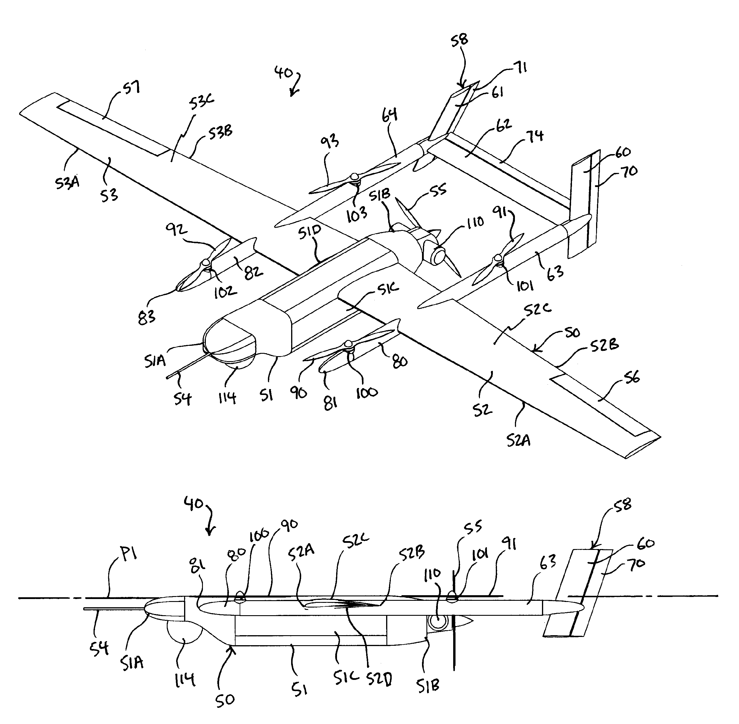
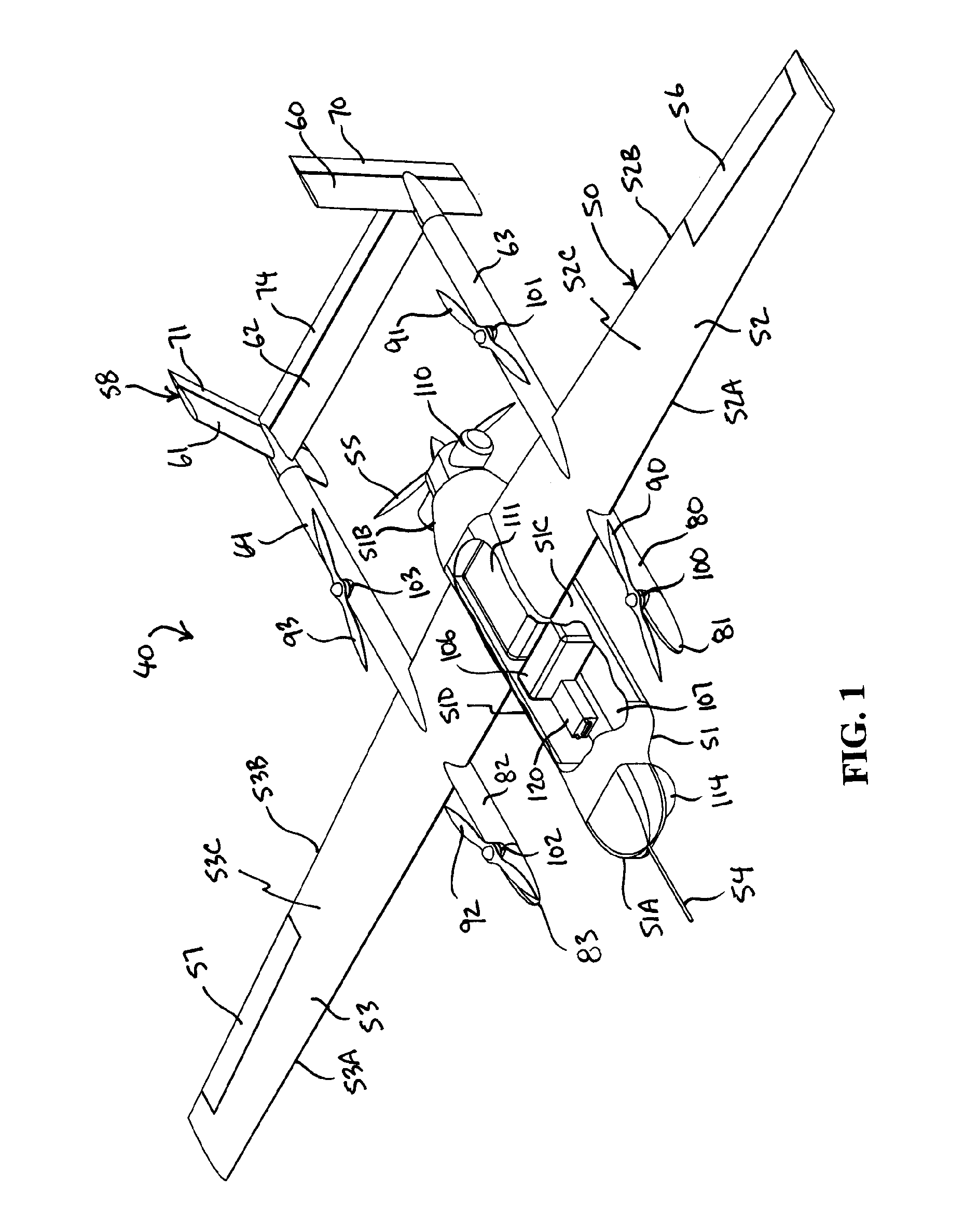
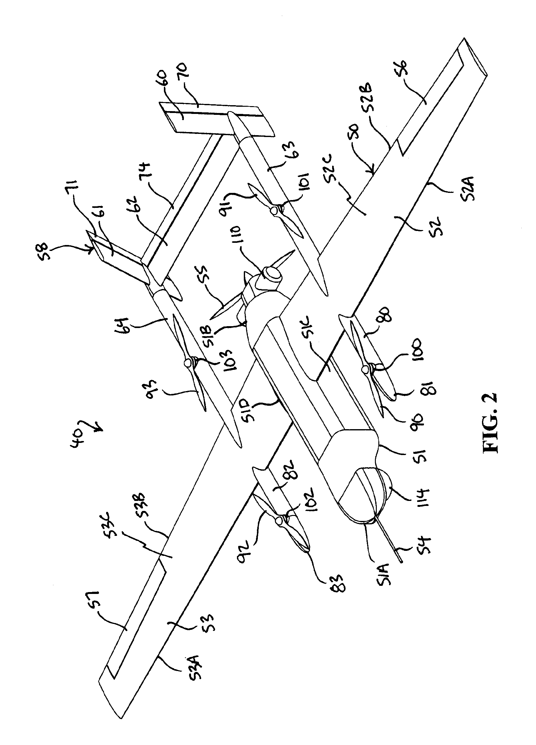
The invention is a vertical take-off and landing aircraft with fixed wings and a unique pattern of four vertical take-off and landing (VTOL) thrust rotors. These rotors are positioned in a quadrotor pattern, with two rotors on each side of the aircraft. The VTOL thrust rotors are driven by electric motors and an internal combustion engine, and they provide vertical lift and forward thrust to the aircraft. The design allows for efficient vertical takeoff and landing, and the aircraft can operate in various modes.

Problems solved by technology

This “tilt-rotor” design is effective but is difficult to engineer and construct, and is inherently unstable between the vertical and horizontal positions of the propellers.
As with the well-known tilt-rotor design, VTOL drones that incorporate redirected thrust systems are difficult to engineer and construct and are inherently unstable between the direct and redirected thrust orientations.
Furthermore, the turbofan / jet engines of redirected thrust VTOL drones are prone to overheating and failure during prolonged VTOL maneuvering, which, of course, prevents redirected thrust VTOL drones from engaging in persistent VTOL maneuvers.
Although this arrangement provides better stability during the transition between VTOL maneuvers and horizontal flight, unwanted buffeting occurs between the thruster housings and the thrusters during VTOL maneuvers, and the thruster housings produce drag and reduce vehicle maneuverability during forward flight operations, which tends causes the horizontal thruster to overheat or otherwise run at unacceptably high temperatures that can lead to a premature and potentially catastrophic engine failure.

Method used


Image

  • Vertical take-off and landing aircraft
  • Vertical take-off and landing aircraft
  • Vertical take-off and landing aircraft

Examples


Embodiment Construction

[0020]In general, disclosed herein is a vertical take-off and landing aircraft that includes fixed wing airframe having opposed left and right wings extending from left and right sides, respectively, of a fuselage having opposed leading and trailing extremities and an empennage located behind the trailing extremity for providing stability to the aircraft. Four fixed, open and horizontal, vertical take-off and landing (VTOL) thrust rotors are mounted to the airframe in a quadrotor pattern for providing vertical lift to the aircraft, and a vertical thrust rotor is mounted to the trailing extremity of the fuselage between the trailing extremity of the fuselage and the empennage for providing forward thrust to the aircraft. The four VTOL thrust rotors are coplanar being and operating in a common plane that is parallel relative to, and being level with, top surfaces of the left and right wings in and around a region of each of the VTOL thrust rotors.

[0021]Turning now to the drawings, in ...


PUM


Abstract

A vertical take-off and landing aircraft includes a fixed wing airframe having opposed left and right wings extending from left and right sides, respectively, of a fuselage having opposed leading and trailing extremities and an empennage located behind the trailing extremity. Four fixed, open and horizontal, vertical take-off and landing (VTOL) thrust rotors are mounted to the airframe in a quadrotor pattern for providing vertical lift to the aircraft, and a vertical, forward thrust rotor is mounted to the trailing extremity of the fuselage between the trailing extremity of the fuselage and the empennage for providing forward thrust to the aircraft. The four VTOL thrust rotors are coplanar being and operating in a common plane that is parallel relative to, and being level with, top surfaces of the left and right wings in and around a region of each of the four VTOL thrust rotors.

Description

FIELD OF THE INVENTION[0001]The present invention relates to aerial vehicles and, more particularly, to unmanned aerial vehicle or drones.BACKGROUND OF THE INVENTION[0002]An unmanned aerial vehicle (UAV), commonly known as a drone, is an aircraft without a human pilot onboard. The flight of a drone is controlled autonomously by computers in the vehicle, or under remote control of a navigator or pilot on the ground or in another vehicle.[0003]One class of drone is the vertical take-off and landing (VTOL) drone. There are many examples of VTOL drones in the prior art. Some exemplary VTOL drones incorporate tilt rotors, such as two large propellers mounted to the ends of an abbreviated wing designed to tilt the propellers from a vertical position for VTOL maneuvering to a horizontal position for normal flight. This “tilt-rotor” design is effective but is difficult to engineer and construct, and is inherently unstable between the vertical and horizontal positions of the propellers. Anot...

Claims


Application Information

Patent Timeline
IPC IPC(8): B64C27/08B64C27/26B64C29/00
CPCB64C29/0008B64C29/0016B64C27/08B64C29/0025B64C27/26B64C39/04B64U10/20B64U50/13B64U30/20
Inventor ARMER, CHARLES JUSTINBIRKINBINE, BAYANI R.CLEARY, THOMAS J.CULBERTSON, SEAN C.DOUGLAS, JASON M.MURPHY, CARLOS V.SINGH, MANU
Owner L3HARRIS UNMANNED SYST INC
Learn More