Seat with adjustable back profile
a back profile and seat technology, applied in the field of seats, can solve the problems of seat not allowing spine deformation correction, seat aches or even spine deformation, and relatively complex and costly construction
- Summary
- Abstract
- Description
- Claims
- Application Information
AI Technical Summary
Benefits of technology
Problems solved by technology
Method used
Image
Examples
first embodiment
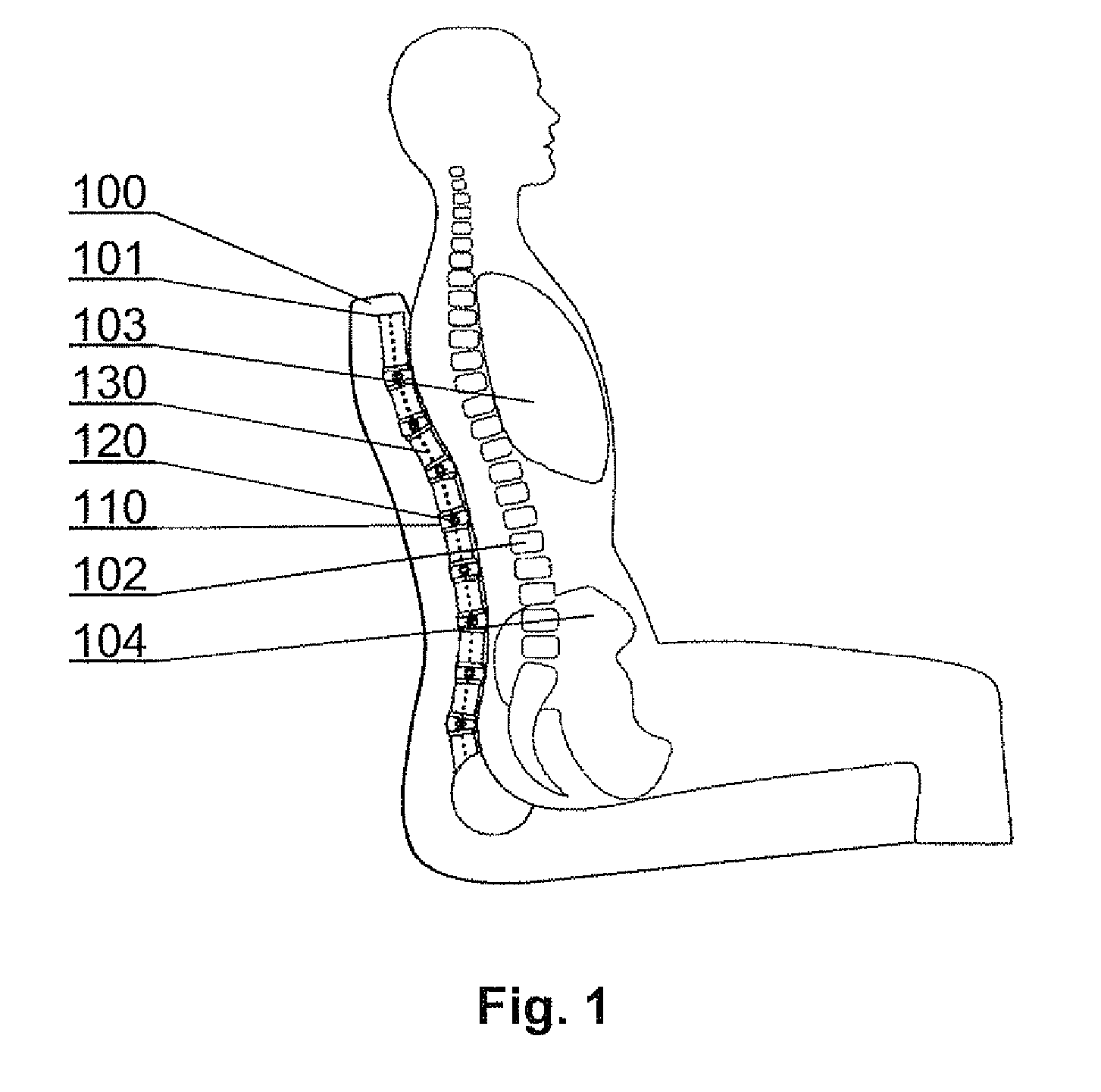
[0031]FIG. 2 shows a configuration of the seat with the back support portion according to the present invention. The adjustable core column 101 comprises a plurality of holders 110 and a plurality of side members 120 fixed to the holders 110. The side members 120 extend substantially in the width direction of the back support portion such as to profile its surface. Profile locking means 130, which in the present embodiment comprise an elastic element 139, preferably inextensible, such as a steel cord, a plastic cord or a chain, are coupled with a plurality of holders 110 and adjustable to an unlocked configuration, in which the holders 110 are individually rotatable around a plurality of axes such that the profile of the surface of the back support portion is adjustable and to a locked configuration, in which the holders 110 are fixed still with respect to each other and the profile of the surface of the back support portion is locked.
[0032]The profile locking means 130 in the prese...
second embodiment
[0035]FIG. 4 shows a configuration of the core column according to the present invention, and FIG. 5 shows exploded view of its structural elements. The core column comprises holders 310 of tubular shape, to which side members 320 are fixed. A spacer 340, preferably in a form of a sphere, is placed between neighboring holders 310 and partially fits inside the tubular holders 310. The holders 310 have a coarse, preferably serrated, top and bottom edges 313, 314 configured to receive partially the spherical spacers 340 having a diameter larger than the internal diameter 316 of the tubular holders 310. The coarse edges 313, 314 of the holders 310 increase the friction between the spacers 340 and the holders 310 in the locked configuration of the core column, thereby fixing still the position of the holders 310 with respect to each other. The spacers 340 have a central through-hole 343 which is preferably narrower than the internal diameter of the holders 310 and preferably substantiall...
third embodiment
[0036]FIG. 6 presents a configuration of the core column according to the invention, and FIGS. 7A and 7B present top and bottom views of the holders used in this embodiment. The core column comprises holders 410 with integrated side elements 420. A spacer 440 having a form of a cylinder with coarse surface is placed between the holders 410 and fits partially into the holders 410. The holders 410 have in their top portion a cylindrical recess 411, in which the spacer 440 can rotate around a horizontal axis, and in their bottom portion a triangular recess 412, in which the spacer 440 can rotate around a vertical axis. Therefore, in the unlocked configuration, the neighboring holders 410 can be rotated with respect to each other both around a horizontal and a vertical axis. The side elements 420 may have longitudinal openings 421 for mounting therein a plate for increasing the profiled back surface, in a range of widths corresponding t the width of the longitudinal opening 421.
[0037]Va...
PUM
 Abstract
Description
Claims
Application Information
 - R&D
- Intellectual Property
- Life Sciences
- Materials
- Tech Scout
- Unparalleled Data Quality
- Higher Quality Content
- 60% Fewer Hallucinations
Browse by: Latest US Patents, China's latest patents, Technical Efficacy Thesaurus, Application Domain, Technology Topic, Popular Technical Reports.
© 2025 PatSnap. All rights reserved.Legal|Privacy policy|Modern Slavery Act Transparency Statement|Sitemap|About US| Contact US: help@patsnap.com


