Eureka AIR delivers breakthrough ideas for toughest innovation challenges, trusted by R&D personnel around the world.

Multi-zone light controller

a multi-zone, light controller technology, applied in the field of light controllers, can solve the problems of reducing intensity and reducing the time of illumination arrangement, and achieve the effect of energy efficien

Active Publication Date: 2015-08-25
KONINK PHILIPS ELECTRONICS NV
View PDF12 Cites 0 Cited by
  • Summary
  • Abstract
  • Description
  • Claims
  • Application Information

AI Technical Summary

Benefits of technology

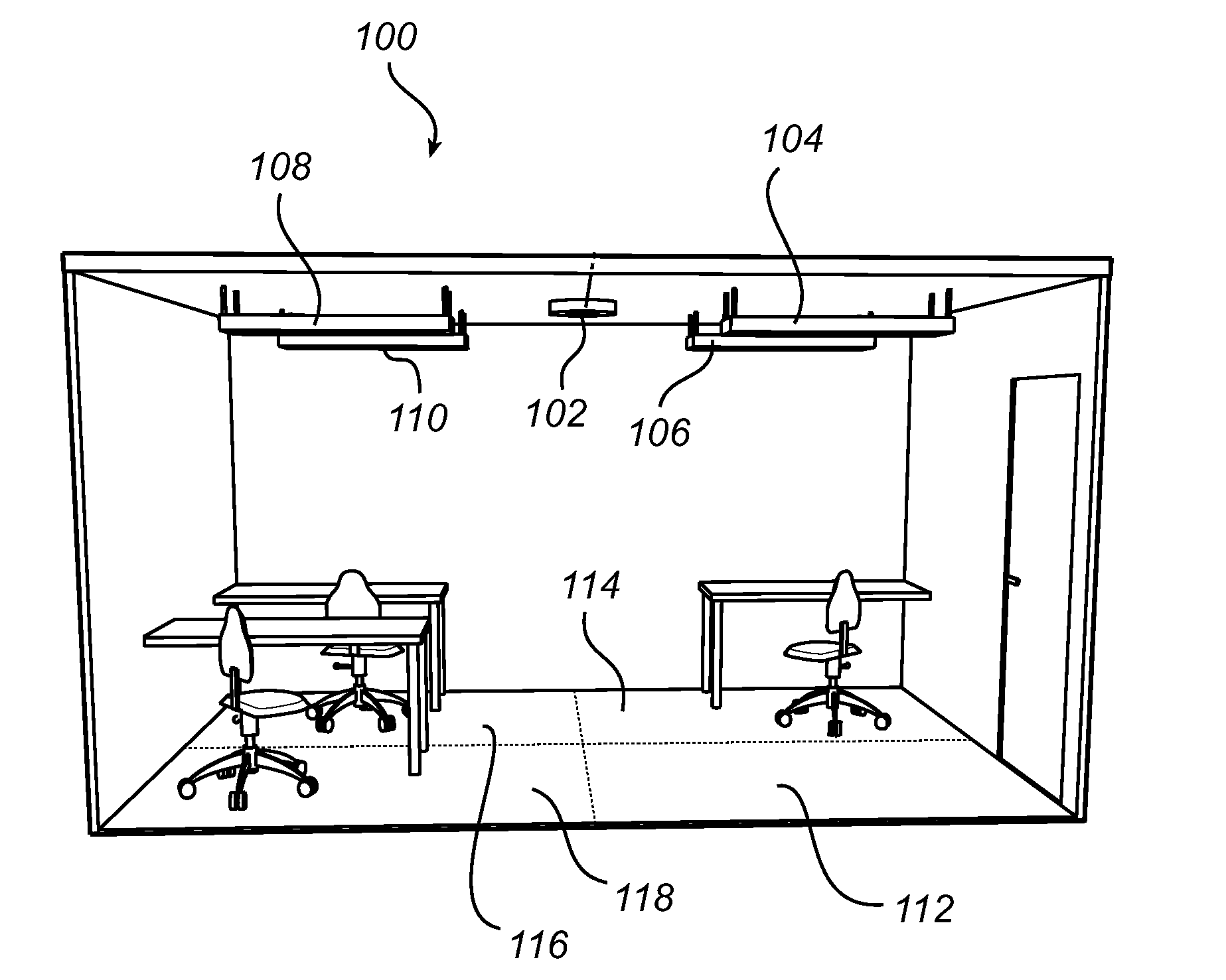
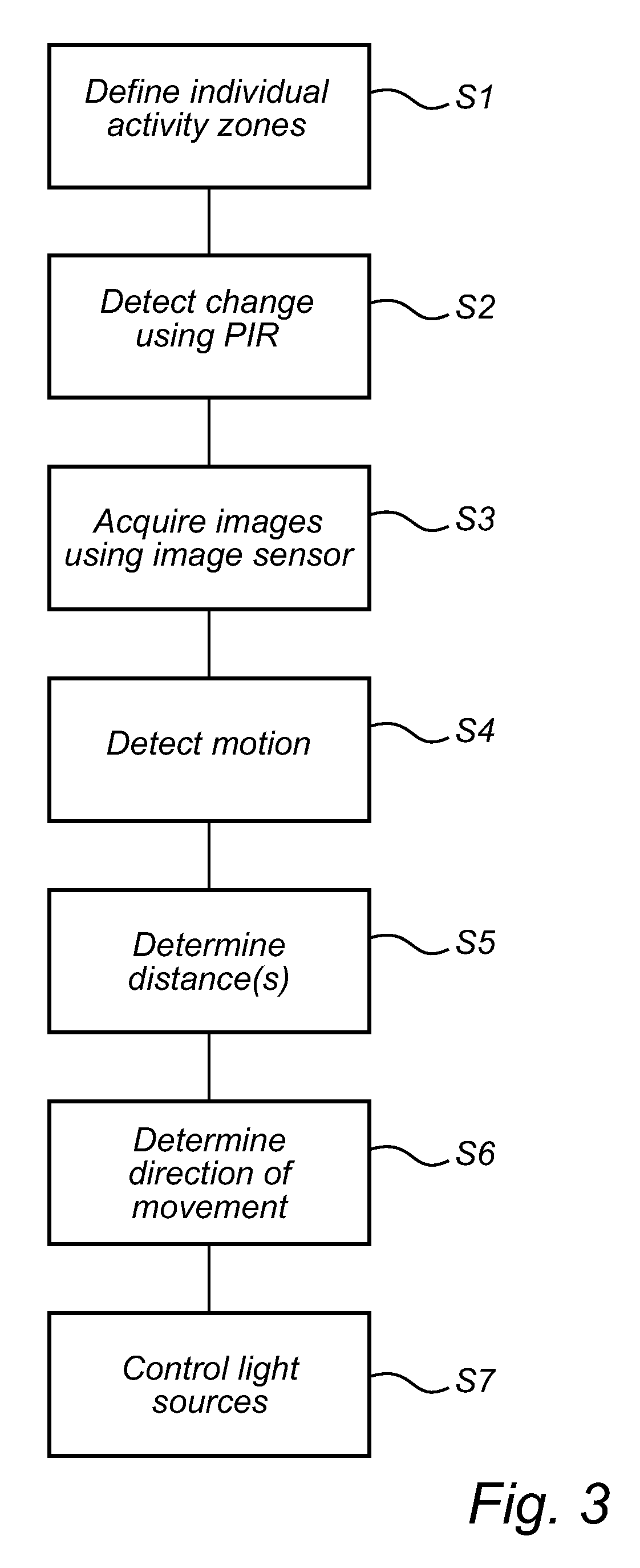
[0007]According to the invention it is possible to optimize the “on time” of the light source of the lighting system by computing where within the activity area motion is detected. This has the advantage that it is possible to further decrease the energy consumption of the lighting system as the time the light source of the lighting system is kept on can be minimized because the light controller “knows” where within the activity area motion is present.
[0008]Advantageously, the computed time period is increased if the computed distance between the predetermined position within the activity area and the position of the latest detected movement within the activity area decreases. Put differently, if for example a person approaches the predetermined position within the activity area, which for example may be the centre of the activity area, the time it takes before the light is turned on is increased. Accordingly, if the person sits down at his desk which preferably may be at the predefined position within the activity area, it will take a long time before it is necessary to again detect any motion before the light is turned off. Conversely, if the person is leaving the room, and thus moves away from the predetermined position, the further the person moves away from the predetermined position the shorter it takes before the light is turned off.
[0009]It should be noted that the computed distance between the predetermined position within the activity area and the position of the latest detected movement within the activity area may comprise a distribution of distances. This may accordingly make it possible to provide “fuzzy” activity areas not necessary being completely round or squared, but rather being optimized for the e.g. office space where the light controller is used. Also, this makes it possible to define portions of the activity area having different rules for computing the time period before the light is turned off.
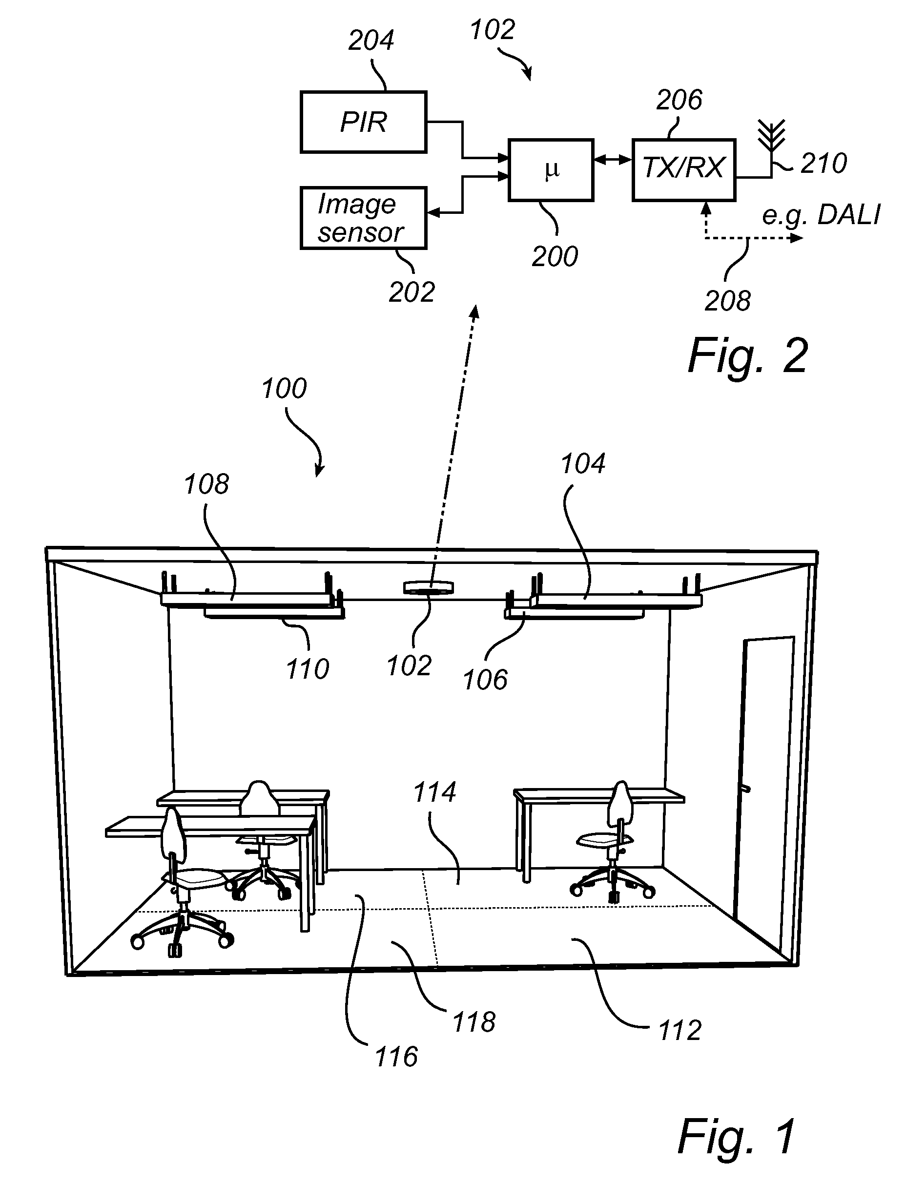
[0010]In a preferred embodiment, the light controller further comprises a passive infrared sensor (for example integrated in a PIR-based motion detector) connected to the control unit. By also equipping the light controller with a passive infrared sensor it is possible to configure the light controller to only capture images, for example by only selectively activate the image sensor, if the passive infrared sensor detects a change in a measured infrared light radiating. Using such an approach has the advantages that the light controller may be made very energy efficient as the image sensor is only activated when the passive infrared sensor detects an actual motion within the activity area. As understood by the skilled person, the passive infrared sensor generally only provides a “digital on / off signal” when motion is detected, whereas the motion sensor may provide a more detailed view (e.g. pixilated) of the activity area.

Problems solved by technology

Such additions may in turn lead to a decrease in the time the illumination arrangement is active, as well as an intensity decrease by taking into account the ambient lighting.

Method used


Image

  • Multi-zone light controller
  • Multi-zone light controller
  • Multi-zone light controller

Examples


Embodiment Construction

[0021]The present invention will now be described more fully hereinafter with reference to the accompanying drawings, in which currently preferred embodiments of the invention are shown. This invention may, however, be embodied in many different forms and should not be construed as limited to the embodiments set forth herein; rather, these embodiments are provided for thoroughness and completeness, and fully convey the scope of the invention to the skilled addressee. Like reference characters refer to like elements throughout.

[0022]Referring now to the drawings and to FIGS. 1 and 2 in parallel, there is depicted a lighting system 100 according to an embodiment of the present invention. In the illustrated embodiment, the lighting system 100 comprises a light controller 102 arranged f.i. in the ceiling of an office space comprising a plurality of desks and arranged to be used by a plurality of persons. The lighting system 100 further comprises a plurality of light sources 104, 106, 10...


PUM


Abstract

The present invention relates to a light controller (102) configured to control a lighting system (100) for emitting light, comprising an image sensor (202) configured to capture an image of an activity area, and a control unit (200) configured to received the image, to detecting movement within the activity area, and to provide an activation signal for switching on a light source (104, 106, 108, 110) of the lighting system (100), wherein the control unit (200) is further configured to provide a deactivation signal for switching off the light source (104, 106, 108, 110) after a computed time period if no movement is detected within the activity area, the computed time period being based on a computed distance between a predetermined position within the activity area and a position of the latest detected movement within the activity area. The present invention provides advantages in relation to e.g. optimized “on time” of the light source of the lighting system thereby providing an improvement in relation to the total energy consumption of the lighting system.

Description

TECHNICAL FIELD[0001]The present invention relates to a light controller for a lighting system, specifically in relation to a lighting system being configured to adaptively control where and during what time periods the lighting system emit light within an activity area, such as an office space. The invention also relates to a corresponding method for controlling a lighting system.BACKGROUND OF THE INVENTION[0002]Recently, much progress has been made in increasing the brightness of light emitting diodes (LEDs). As a result, LEDs have become sufficiently bright and inexpensive, to serve as a light source in for example illumination arrangements such as lamps with adjustable color. By mixing differently colored LEDs any number of colors can be generated, e.g. white. An adjustable color lighting system is typically constructed by using a number of primary colors, and in one example, the three primaries red, green and blue are used. The color of the generated light is determined by the ...

Claims


Application Information

Patent Timeline
Patent Type & Authority Patents(United States)
IPC IPC(8): H05B37/02H05B39/04H05B41/36H05B33/08H05B44/00
CPCH05B33/0854H05B37/0227H05B37/0245H05B37/0272H05B47/175H05B47/19H05B47/125H05B47/13H05B45/12Y02B20/40
Inventor ZNAMENSKIY, DMITRY NIKOLAYEVICHABBO, ANTENEH ALEMU
Owner KONINK PHILIPS ELECTRONICS NV
Why Eureka
Eureka Blog
Learn More