Reverse electrodialysis supported microbial fuel cells and microbial electrolysis cells

a technology of microbial fuel cells and reverse electrodialysis, which is applied in the direction of electrodialysis, refrigeration components, energy input, etc., can solve the problems of limited electrical linking of mfc reactors in series, no method or device is believed to have been developed prior to the invention of the first generation

Active Publication Date: 2015-08-18
PENN STATE RES FOUND
View PDF4 Cites 18 Cited by
  • Summary
  • Abstract
  • Description
  • Claims
  • Application Information

AI Technical Summary

Benefits of technology

[0021]Microbial processes for generating a product are provided according to aspects of the present invention which include providing a system including a reaction chamber having a wall defining an interior of the reaction chamber and an exterior of the reaction chamber; an anode at least partially contained within an anode compartment of the reaction chamber; a plurality of exoelectrogenic microorganisms disposed in the anode compartment; a cathode at least partially contained within a cathode compartment of the reaction chamber; a conductive conduit for electrons in electrical communication with the anode and the cathode; and a first reverse electrodialysis stack comprising a plurality of plurality of alternating anion selective barriers and cation selective barriers disposed between the anode and the cathode defining one or more saline material compartments and one or more lower-saline material compartments; introducing a material oxidizable by an oxidizing activity of the exoelectrogenic microorganisms into the anode chamber; incubating the material oxidizable by the exoelectrogenic microorganisms under oxidizing reactions conditions such that electrons are produced and transferred to the anode, generating a potential between the anode and cathode; introducing a saline material having a concentration of dissolved salts into the saline material compartment; and introducing a lower-saline material having a concentration of dissolved salts which is lower than the saline material into the lower-saline material compartment, wherein an electromotive force established by a difference in the concentration of dissolved salts in the saline material compared to the lower-saline material (the saline ratio) drives ions across the first anion selective barrier and first cation selective barrier, wherein the saline ratio between the saline material and the lower-saline material introduced into the saline material compartment and lower-saline material compartment is greater than 1:1, thereby increasing the potential between the anode and cathode, decreasing the concentration of dissolved salts in the saline material to generate a saline material effluent, and increasing the concentration of dissolved salts in the lower-saline material to generate a lower-saline material effluent.
[0026]Heating the lower-saline material effluent to volatize and remove the thermolytic salt, such as ammonium bicarbonate, according to aspects of the present invention includes heating to temperature sufficient to volatilize the thermolytic salt and thereby separate it from the solvent, typically water. Heating an aqueous solution including ammonium bicarbonate to a temperature in the range of about 50-90° C. volatilizes the ammonium bicarbonate and thereby separates it from water without substantial vaporization of the water.

Problems solved by technology

Ordinary fuel cells (i.e. PEM hydrogen fuel cells) can be linked in series to increase voltage, but when MFCs are electrically linked in series there is a voltage reversal, and the power output from the stack (multiple cells in series) is not consistently increased in proportion to the number of cells.
This electrical linking of MFC reactors in series has limited applications where higher voltages are desired.
However, no method or device is believed to have been developed prior to the present invention to directly achieve H2 production in one biotic process without an external voltage supply.

Method used


Image

  • Reverse electrodialysis supported microbial fuel cells and microbial electrolysis cells
  • Reverse electrodialysis supported microbial fuel cells and microbial electrolysis cells
  • Reverse electrodialysis supported microbial fuel cells and microbial electrolysis cells

Examples


example 1

MRC Construction

[0250]For the outer chambers of the MRC, two blocks of Lexan were drilled to make a cylindrical cathode (18 mL) and anode (30 mL) chambers with a cross-sectional area of 7 cm2. The air cathode was prepared with a platinum catalyst on the water side (3.5 mg Pt over 7 cm2) with a Nafion binder, and four polytetrafluoroethylene diffusion layers were coated on the air side. The anode, a graphite fiber brush 2.7 cm in diameter and 2.3 cm long (Mill-Rose Lab Inc., OH), was inoculated with effluent from an existing MFC and enriched by operation in a conventional single chamber MFC. During this start-up stage, NaCl concentration was gradually raised so that the microbial activity would not be affected by salinity during the following MRC operation.

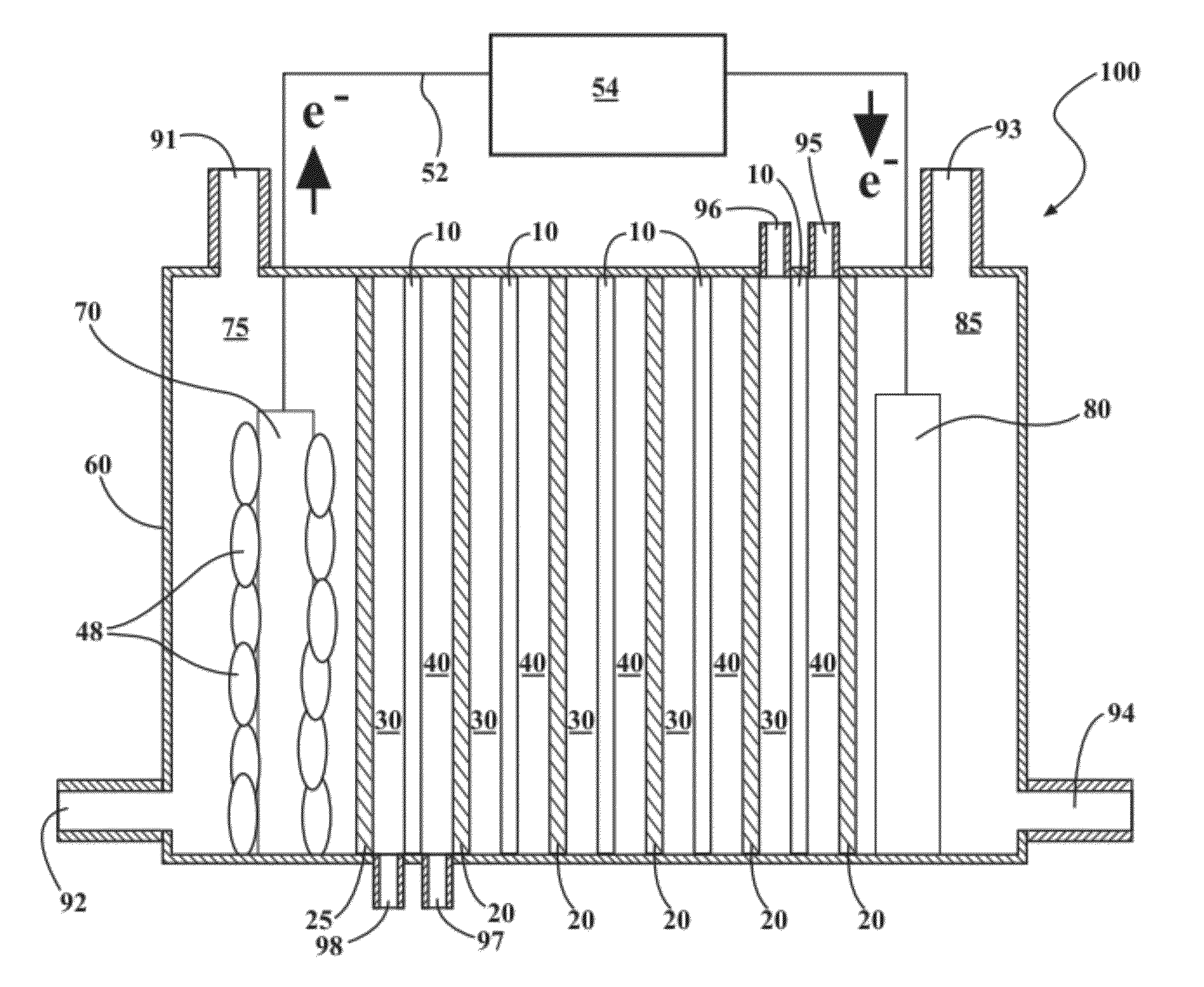
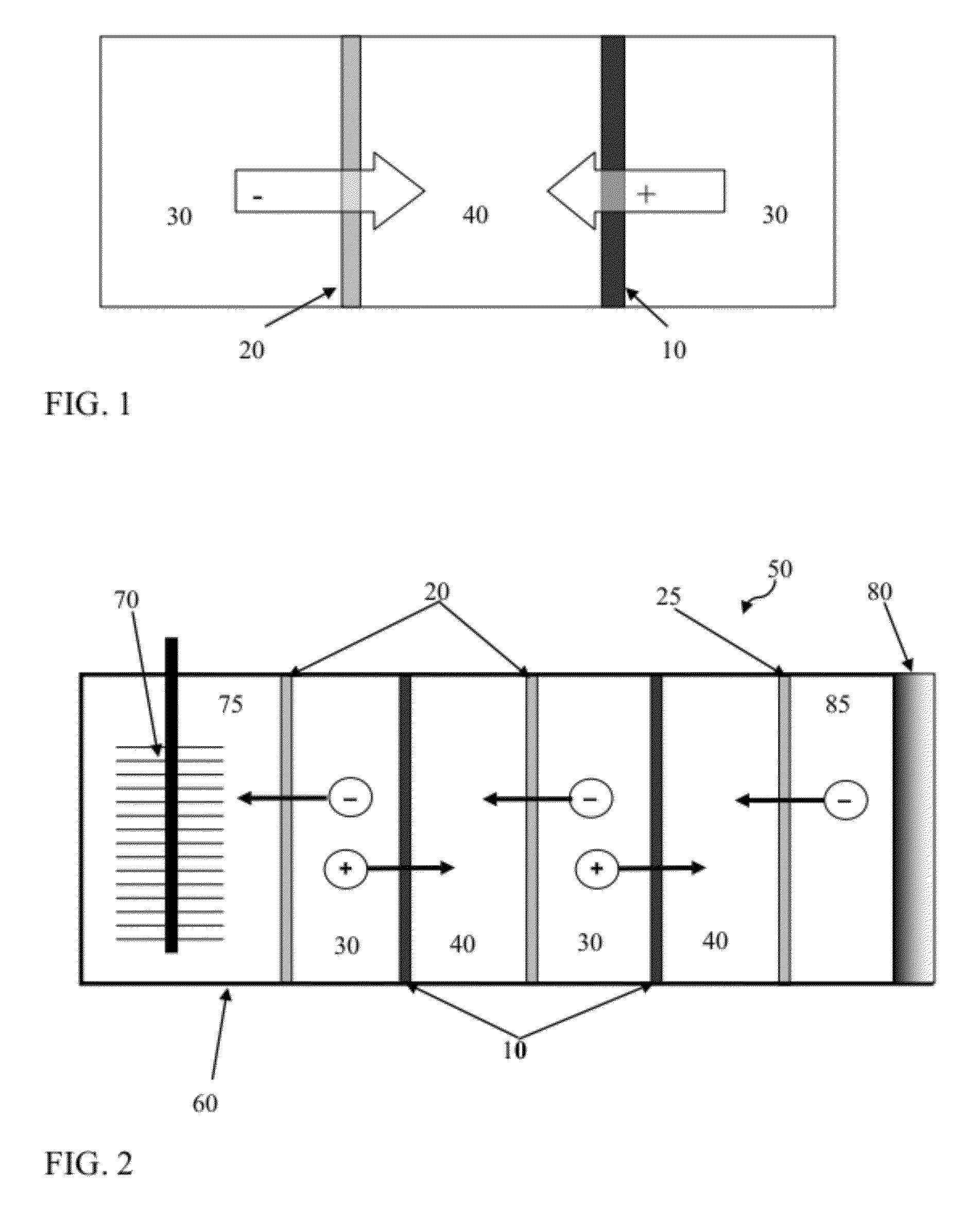
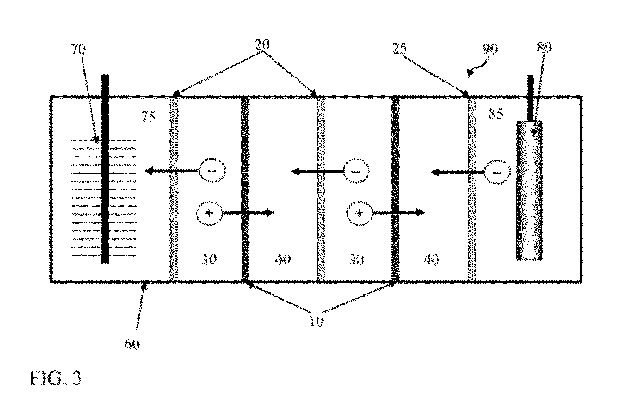
[0251]The RED stack in this example included 10 cells (called subunits herein) in total, with 5 seawater cells (saline material compartments) and 5 river water cells (lower-saline material compartments) alternately sandwiched betwe...

example 2

MREC Construction

[0293]A cubic Lexan block with a cylindrical chamber (˜30 mL; 7 cm2 in cross section) was used for an anode and cathode container, with a glass tube (20 mL) glued to the top of the cathode chamber to collect H2. The stainless steel mesh (SS) cathode was prepared with platinum (0.6 mg / cm2; BASF, Germany) as the catalyst (except as indicated) in a mixture of carbon black and Nafion on both sides of a 7-cm2 stainless steel mesh (#50). In some tests the SS cathode was prepared with MoS2 (6.3 mg / cm2) as a replacement of the Pt catalyst. The carbon cloth (CC) cathode was made with a Pt catalyst (0.5 mg / cm2) in the same manner using a 7-cm2 piece of carbon cloth. The anode (a graphite fiber brush 2.7 cm in diameter and 2.3 cm in length; Mill-Rose Lab Inc., OH) was inoculated with the effluent from an existing MFC and initially enriched in a single chamber MFC. During this start-up stage, the anode microbes were acclimated to a gradually increase in NaCl concentration to av...

example 3

[0352]FIG. 7 illustrates a process of the current invention where effluent circulated through the RED stack is regenerated in a distillation column into a saline material (regenerated concentrate solution) and a lower-saline material (regenerated dilute solution). Here the anode and cathode solutions are shown as once-through, but they can be recycled.

[0353]FIG. 15 illustrates model results by using Eq. (1). The model results obtained using Eq. 1, and shown in FIG. 15, indicate that the NH4HCO3 concentration in the concentrate solution (saline material) should be greater than ˜0.5 molal, but a concentration greater than 1 molal does not significantly improve the cell potential. For the model simulation, the transport numbers were: tcounter=0.9 and tco=0.1. The activity coefficients were determined by Pitzer equation with parameters of KHCO3 by (Pitzer and Pelper, 1980).


PUM

PropertyMeasurementUnit
external voltageaaaaaaaaaa
temperatureaaaaaaaaaa

Abstract

Systems and methods for microbial processes of generating products such as electrical power, hydrogen gas and methane, are provided according to aspects of the present invention which include a reaction chamber having a wall defining an interior of the reaction chamber and an exterior of the reaction chamber; an anode at least partially contained within an anode compartment of the reaction chamber; a plurality of exoelectrogenic microorganisms disposed in the anode compartment; a cathode at least partially contained within a cathode compartment of the reaction chamber; a conductive conduit for electrons in electrical communication with the anode and the cathode; and a reverse electrodialysis stack comprising a plurality of plurality of alternating anion selective barriers and cation selective barriers disposed between the anode and the cathode defining one or more saline material compartments and one or more lower-saline material compartments.

Description

REFERENCE TO RELATED APPLICATIONS[0001]This application claims priority from U.S. Provisional Patent Application Ser. No. 61 / 487,107, filed May 17, 2011; 61 / 544,067, filed Oct. 6, 2011; and 61 / 598,635, filed Feb. 14, 2012. The entire content of each application is incorporated herein by reference.FIELD OF THE INVENTION[0002]Microbial systems incorporating reverse electrodialysis for generation of products such as power or hydrogen are provided according to embodiments of the present invention.BACKGROUND OF THE INVENTION[0003]A microbial fuel cell (MFCs) is a type of bioelectrochemical system (BES) where current is generated by bacteria from the oxidation of organic and inorganic matter. Compounds are reduced at the cathode, such as oxygen or protons, through inorganic catalysts or bacteria and electrical power is generated in an MFC.[0004]Ordinary fuel cells (i.e. PEM hydrogen fuel cells) can be linked in series to increase voltage, but when MFCs are electrically linked in series th...

Claims


Application Information

Patent Timeline
Patent Type & Authority Patents(United States)
IPC IPC(8): H01M8/16B01D61/44B01D61/46H01M8/22B01D61/50
CPCH01M8/227B01D61/44B01D61/50H01M8/16Y02E10/36Y02E60/527C25B1/02Y02P20/129Y02E60/50C25B9/19Y02E10/30
Inventor KIM, YOUNGGYCUSICK, ROLAND D.LOGAN, BRUCE
Owner PENN STATE RES FOUND
Why Eureka
Try Eureka