
Shoe insole

a technology of insoles and shoes, applied in the direction of uppers, bootlegs, stiffners, etc., to achieve the effect of eliminating the disability caused by the distortion of basal foot joints, stable center of gravity, and suitable movemen

Inactive Publication Date: 2015-08-18
KITAGAWA HIROYUKI
View PDF23 Cites 2 Cited by
  • Summary
  • Abstract
  • Description
  • Claims
  • Application Information

AI Technical Summary

Benefits of technology

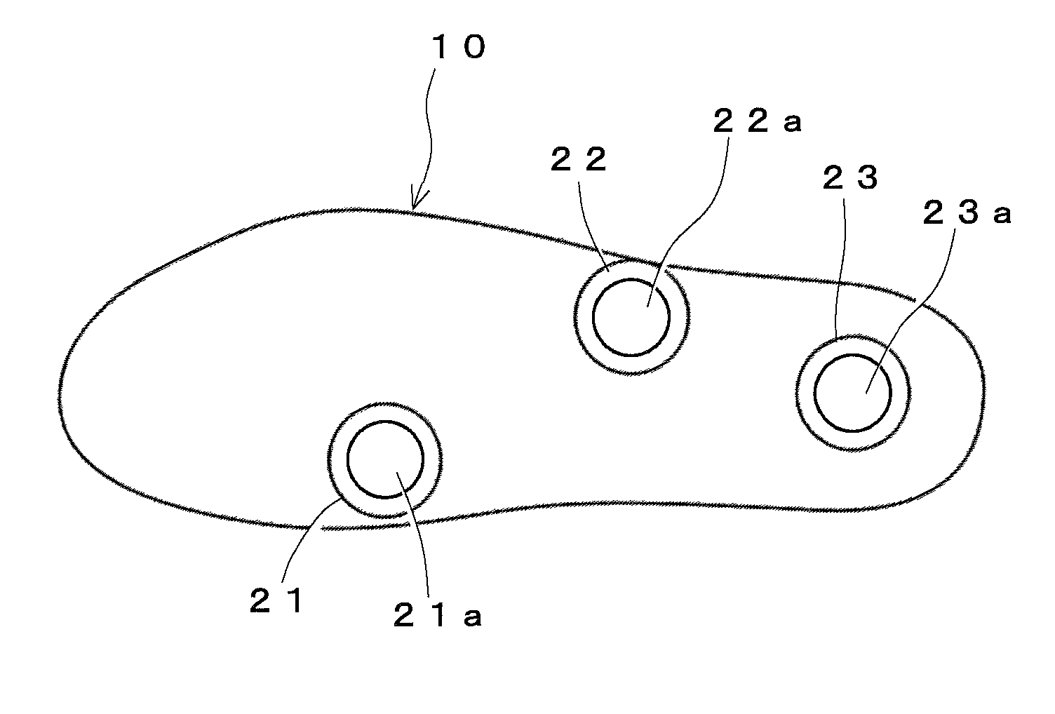
[0011]It is an object of the present invention to provide an insole by which suitable movements and a stable balance are made possible. For this object, an insole of the present invention is completed by considering skeletons, foot joint movements, and a center of gravity when feet are grounded, so that a three point balance in which a first metatarsal sesamoid bone, a tuberosity of fifth metatarsal bone, and a calcaneal tuberosity are used as supporting points is constituted.
[0012]An object of the insole described in the Patent Literature 1 is to prevent hallux valgus. The insole has concave and convex portions to fix a foot in a shoe without movements, and thereby hallux valgus will be prevented.
[0017]An insole of the present invention has a planar contour shape whose outer edge is fitted along with an edge of the inside of a shoe, so that the insole can be on a certain position when placed into the shoe. A three-dimensional shape of the insole has convex portions on particular positions. The convex portions are located on positions that support a first metatarsal sesamoid bone, a tuberosity of fifth metatarsal bone, and a calcaneal tuberosity from a sole side. This three point balance is most preferable, since it is the most stable manner of support as shown by tripod stands. According to the present invention, sequential disabilities caused by distortions of basal foot joints can be eliminated.
[0018]According to the present invention, a shoe insole, which supports a sole at three points thereof, so that a stable center of gravity and suitable movements are made possible can be provided.
[0019]In particular, the shoe insole can improve functional movements as it supports a sole at appropriate positions for three point balancing, which stabilizes a center of gravity and keeps a right position. In addition, an insole of the present invention can eliminate sequential disabilities caused by distortions of basal foot joints.

Problems solved by technology

However, in the insole described in the Patent Literature 1, structures of foot joints are not considered, and the insole is not designed to support particular sites, and allow suitable movements.

Method used


Image

  • Shoe insole
  • Shoe insole
  • Shoe insole

Examples


Embodiment Construction

[0028]Hereinafter, an embodiment of an insole according to the present invention will be explained by reference to the figures.

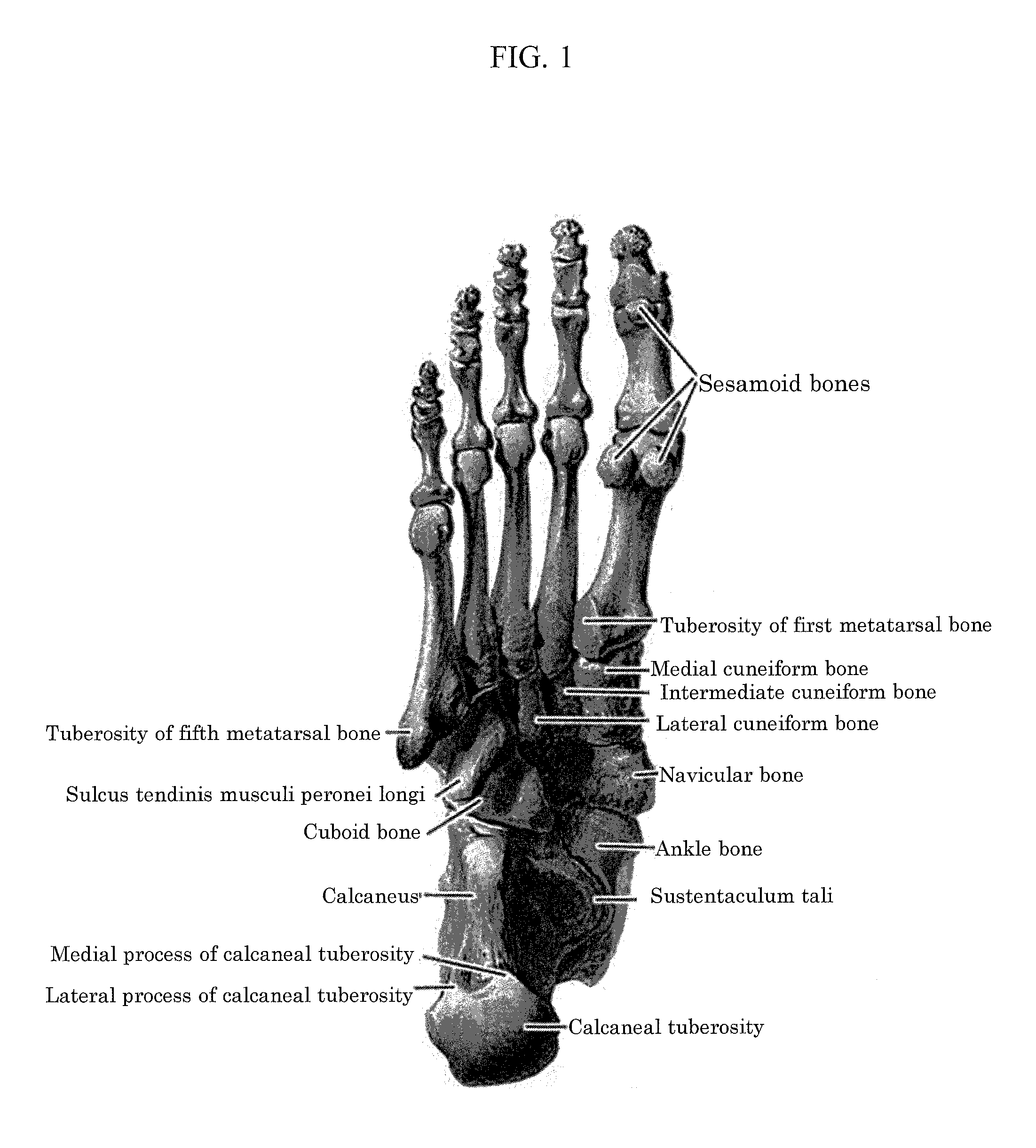
[0029]Although FIGS. 1 and 3 show bones of a right sole and an insole for a right sole, bones of a left sole and an insole for a left sole are mirror image objects.

[0030]A shoe insole of the present invention is to improve functional movements by improving a standing position and adjusting a center of gravity, and thus the insole is suitable not only for shoes routinely used, but also for functional shoes used on sports and the like.

[0031]Firstly, a skeletal structure of a foot will be explained to subsequently explain an embodiment of an insole of the present invention, regarding a structure, a function, and an action of the insole. FIG. 1 is a plan view illustrating a skeletal structure of a sole. This drawing is viewed from a bottom side.

[0032]FIG. 3 shows the shoe insole 10 having characteristic portions to stabilize a center of gravity by a three point ...


PUM


Abstract

A shoe insole, which supports three points on a sole to stabilize a center of gravity, is provided by considering a skeletal structure of a foot and a sequential movement from foot joints to a body. The three points, which are a first metatarsal sesamoid bone, tuberosity of fifth metatarsal bone, and a calcaneal tuberosity, are supported from a sole side, and the three point balance can stabilize a center of gravity, and thereby a stimulus that adjusts body movements derived from a sole to help a body to be back to a right position can be given.

Description

BACKGROUND OF THE INVENTION[0001]1. Field of the Invention[0002]The present invention relates to a shoe insole. More particularly, the present invention relates to a shoe insole supporting a sole at three points thereof, so that a stable center of gravity and suitable movements are made possible.[0003]2. Description of the Related Art[0004]Although some shoe insoles are used mainly for deodorizing and comforting purposes, a shoe insole of the present invention is considering of balancing to keep a right position and adjust a center of gravity for functional movements.[0005]When foot joints are distorted, skeletal, muscular, and nervous systems may adversely be affected. Skeletal systems are affected, such that when basal foot joints are distorted, differences in heights will be made to the right and left pelvises, which may subsequently cause scoliosis to a backbone. The scoliosis of a backbone may cause a variety of systemic impairments, such as neurological disorders, blood circul...

Claims


Application Information

Patent Timeline
Patent Type & Authority Patents(United States)
IPC IPC(8): A43B7/14
CPCA43B7/14A43B7/143A43B7/144A43B7/1405A43B7/149A43B7/1425
Inventor KITAGAWA, HIROYUKI
Owner KITAGAWA HIROYUKI
Learn More