
Catheter control systems

a control system and catheter technology, applied in the field of catheter control systems, can solve the problems of difficult manipulation, difficult to achieve the effect of maximizing the control of the hood position, and difficult to keep track of the orientation of the deflection of the hood

Active Publication Date: 2015-08-11
INTUITIVE SURGICAL OPERATIONS INC
View PDF569 Cites 17 Cited by
  • Summary
  • Abstract
  • Description
  • Claims
  • Application Information

AI Technical Summary

Benefits of technology

[0017]The catheter shaft contains at least one lumen which allows the passage of one or more pullwires that are connected to the steering member at the proximal end of the pullwire while the distal end may be terminated and anchored to the steering mechanisms along the steerable portion of the catheter. A compression coil, e.g., made of stainless steel, with a slightly larger diameter than the pullwire may be positioned about the pullwire within the handle to allow the pullwire to slide freely therethrough.
[0019]The handle assembly may also optionally incorporate an optical adjustment assembly which may be used to move the distal lens of a visualization instrument, such as a fiberscope, distally or proximally from the imaged tissue region, hence simulating a zoom-in and / or zoom-out optical effect. Generally, the optical adjustment assembly is able to provide zoom-in and / or zoom-out capabilities by varying the length of the assembly. By rotating an adjustment member, which is coupled to a retaining sleeve within the optical adjustment assembly, a distal shaft portion may be advanced or retracted relative to the guide shaft. The assembly may be accordingly varied in length while distally or proximally advancing the fiberscope based on the varied length of the optical adjustment assembly to control the visualized field of view.
[0020]Because manipulation of the hood and steerable portion corresponds with an angle at which the handle is positioned, the handle may also serve as an orientation indicator for the hood and steerable portion once the hood has been introduced into the patient's body. This correspondence between the planes of the handle and the resulting articulation of the hood and steerable portion may be particularly useful for efficiently controlling the hood position within the patient's body. As the catheter is usually repeatedly torqued during a procedure, keeping track of the orientation of the deflection of the hood can be difficult, if not impossible, unless fluoroscopy is used. With the handle, the angle of deflection of the hood can be predicted by the operator without the need of fluoroscopy. This is can be particularly desirable in procedures such as transseptal punctures where an accurate angle of puncture of the septal wall is desirable to avoid complications such as perforation of the aorta.
[0023]Although multiple pullwires may be utilized depending upon the number of directions for articulation, four pullwires may be typically utilized. Each of the four pullwires may be terminated symmetrically around a circumference of the steering ring such that a balanced four-way steering of the distal portion may be accomplished, although manipulating the steering ring along various portions of its circumference may yield combinational articulation between the pullwires to result in numerous catheter configurations. Additionally, the handle assembly may further incorporate a spring mechanism as an overdrive prevention mechanism positioned between the transition manifold and ball pivot in order to prevent over-tensioning or breaking of the pullwires if the steering ring is over-deflected in a direction.

Problems solved by technology

However, many of the conventional catheter imaging systems lack the capability to provide therapeutic treatments or are difficult to manipulate in providing effective therapies.
For instance, the treatment in a patient's heart for atrial fibrillation is generally made difficult by a number of factors, such as visualization of the target tissue, access to the target tissue, and instrument articulation and management, amongst others.
Conventional catheter techniques and devices, for example such as those described in U.S. Pat. Nos. 5,895,417; 5,941,845; and 6,129,724, used on the epicardial surface of the heart may be difficult in assuring a transmural lesion or complete blockage of electrical signals.
In addition, current devices may have difficulty dealing with varying thickness of tissue through which a transmural lesion is desired.
Conventional accompanying imaging devices, such as fluoroscopy, are unable to detect perpendicular electrode orientation, catheter movement during the cardiac cycle, and image catheter position throughout lesion formation.
The absence of real-time visualization also poses the risk of incorrect placement and ablation of structures such as sinus node tissue which can lead to fatal consequences.
Moreover, because of the tortuous nature of intravascular access, devices or mechanisms at the distal end of a catheter positioned within the patient's body, e.g., within a chamber of the heart, are typically no longer aligned with the handle.
Steering or manipulation of the distal end of the catheter via control or articulation mechanisms on the handle is easily disorienting to the user as manipulation of a control on the handle in a first direction may articulate the catheter distal end in an unexpected direction depending upon the resulting catheter configuration leaving the user to adjust accordingly.
However, this results in reduced efficiency and longer procedure times as well as increased risks to the patient.

Method used


Image

  • Catheter control systems
  • Catheter control systems
  • Catheter control systems

Examples


Embodiment Construction

[0066]A tissue-imaging and manipulation apparatus described herein is able to provide real-time images in vivo of tissue regions within a body lumen such as a heart, which is filled with blood flowing dynamically therethrough and is also able to provide intravascular tools and instruments for performing various procedures upon the imaged tissue regions. Such an apparatus may be utilized for many procedures, e.g., facilitating transseptal access to the left atrium, cannulating the coronary sinus, diagnosis of valve regurgitation / stenosis, valvuloplasty, atrial appendage closure, arrhythmogenic focus ablation, among other procedures.

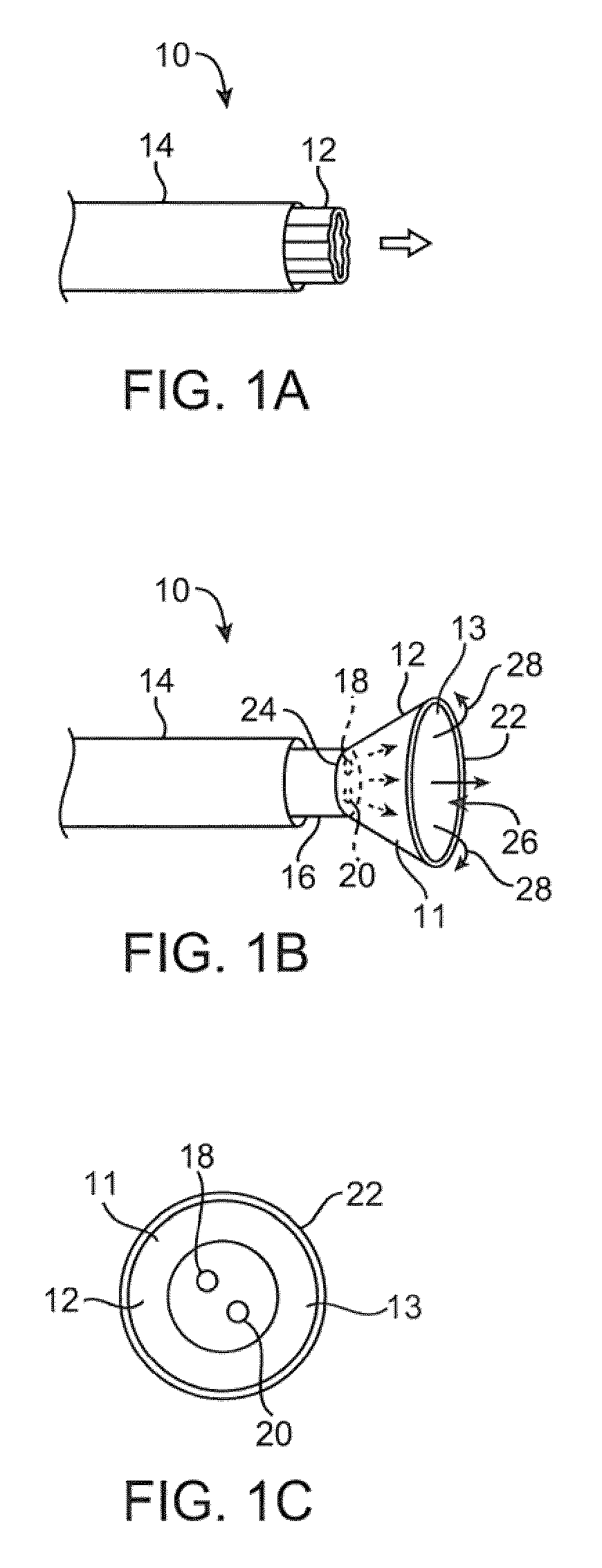
[0067]One variation of a tissue access and imaging apparatus is shown in the detail perspective views of FIGS. 1A to 1C. As shown in FIG. 1A, tissue imaging and manipulation assembly 10 may be delivered intravascularly through the patient's body in a low-profile configuration via a delivery catheter or sheath 14. In the case of treating tissue, it is gener...


PUM


Abstract

Catheter control systems which facilitate the tracking of an angle of deflection of a catheter distal end can be used for any number of procedures where catheter orientation relative to the body is desirable, e.g., in transseptal access procedures where an accurate angle of puncture of the septal wall is desirable. Such control systems may comprise a steerable handle which is oriented relative to the catheter steerable section to provide for consistent catheter articulation upon corresponding manipulation of the steering ring. Another variation may utilize an orientation indicator to track the deflectable distal end. For instance, an orientation marker as visualized through an imaging hood on the distal end may correspond to identical orientation markers on the control handle such that articulation of a steering mechanism in a direction relative to the orientation markers deflects the catheter distal end in a corresponding direction relative to the visualized orientation markers.

Description

CROSS-REFERENCE TO RELATED APPLICATIONS[0001]This application claims the benefit of priority to U.S. Prov. Pat. App. 61 / 078,746 filed Jul. 7, 2008, which is incorporated herein by reference in its entirety.FIELD OF THE INVENTION[0002]The present invention relates generally to catheter control systems for controlling the articulation of visualization and treatment apparatus having imaging and manipulation features for intravascularly accessing regions of the body.BACKGROUND OF THE INVENTION[0003]Conventional devices for accessing and visualizing interior regions of a body lumen are known. For example, various catheter devices are typically advanced within a patient's body, e.g., intravascularly, and advanced into a desirable position within the body. Other conventional methods have utilized catheters or probes having position sensors deployed within the body lumen, such as the interior of a cardiac chamber. These types of positional sensors are typically used to determine the movemen...

Claims


Application Information

Patent Timeline
Patent Type & Authority Patents(United States)
IPC IPC(8): A61B1/01A61M25/01A61M25/00
CPCA61M25/0147A61M25/0136A61M25/0074A61M25/0082A61M25/0105A61M2025/015A61B1/0052A61B1/0055A61B1/0051
Inventor ROTHE, CHRIS A.PEREA, JUAN DIEGOMILLER, DAVIDSAADAT, VAHIDMALCHANO, ZACHARY J.PEH, RUEY-FENG
Owner INTUITIVE SURGICAL OPERATIONS INC
Learn More