Stereoscopic display device, system and method

a liquid crystal display and stereoscopic technology, applied in optics, instruments, electrical equipment, etc., can solve the problems of increased manufacturing costs and inconvenien

Active Publication Date: 2011-08-30
WISTRON CORP
View PDF6 Cites 1 Cited by
  • Summary
  • Abstract
  • Description
  • Claims
  • Application Information

AI Technical Summary

Benefits of technology

[0010]Therefore, an object of the present invention is to provide a stereoscopic display device, system, and method capable of achieving a stereoscopic display effect without the need to change the manufacturing process or production equipment so as to overcome the problems associated with the prior art.
[0011]Another object of the present invention is to provide a stereoscopic display device, system, and method capable of simulating a visual effect of relatively high resolution.
[0015]The present invention is also directed to processing of the left eye image signal for display by the first pixel group and of the right eye image signal for display by the second pixel group such that the color displayed by each of the pixels is determined by both the original color of the respective pixel and the colors of adjoining pixels. Thus, the colors of the second pixel group which normally cannot be viewed with the left eye have a contribution to the colors of the first pixel group, and the colors of the first pixel group which normally cannot be viewed with the right eye have a contribution to the second pixel group, so that the left or right eye image presented to the corresponding eye of a wearer of the stereoscopic glasses is closer to the whole image, thereby simulating a visual effect of relatively high resolution.
[0022]The effect of the present invention resides in that the objective of stereoscopic display can be achieved by providing the inner and outer polarizers with specially designed polarization regions.

Problems solved by technology

However, since the conventional stereoscopic display system 9 utilizes the liquid crystal screen 90 that has the micro phase retardation film 91 additionally attached thereto in order to produce a stereoscopic display effect in conjunction with the use of the stereoscopic glasses 92, the manufacture of the stereoscopic display system 9, in comparison with the manufacture of a conventional liquid crystal display screen without the micro phase retardation film 91, requires addition or change of processing steps and adjustment of production line equipment, thereby resulting in increased manufacturing costs and inconvenience.

Method used


Image

  • Stereoscopic display device, system and method
  • Stereoscopic display device, system and method
  • Stereoscopic display device, system and method

Examples


Embodiment Construction

[0030]Before the present invention is described in greater detail, it should be noted that like elements are denoted by the same reference numerals throughout the disclosure.

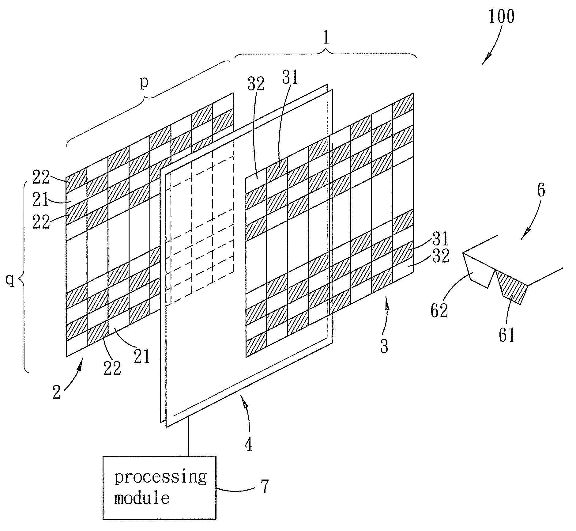
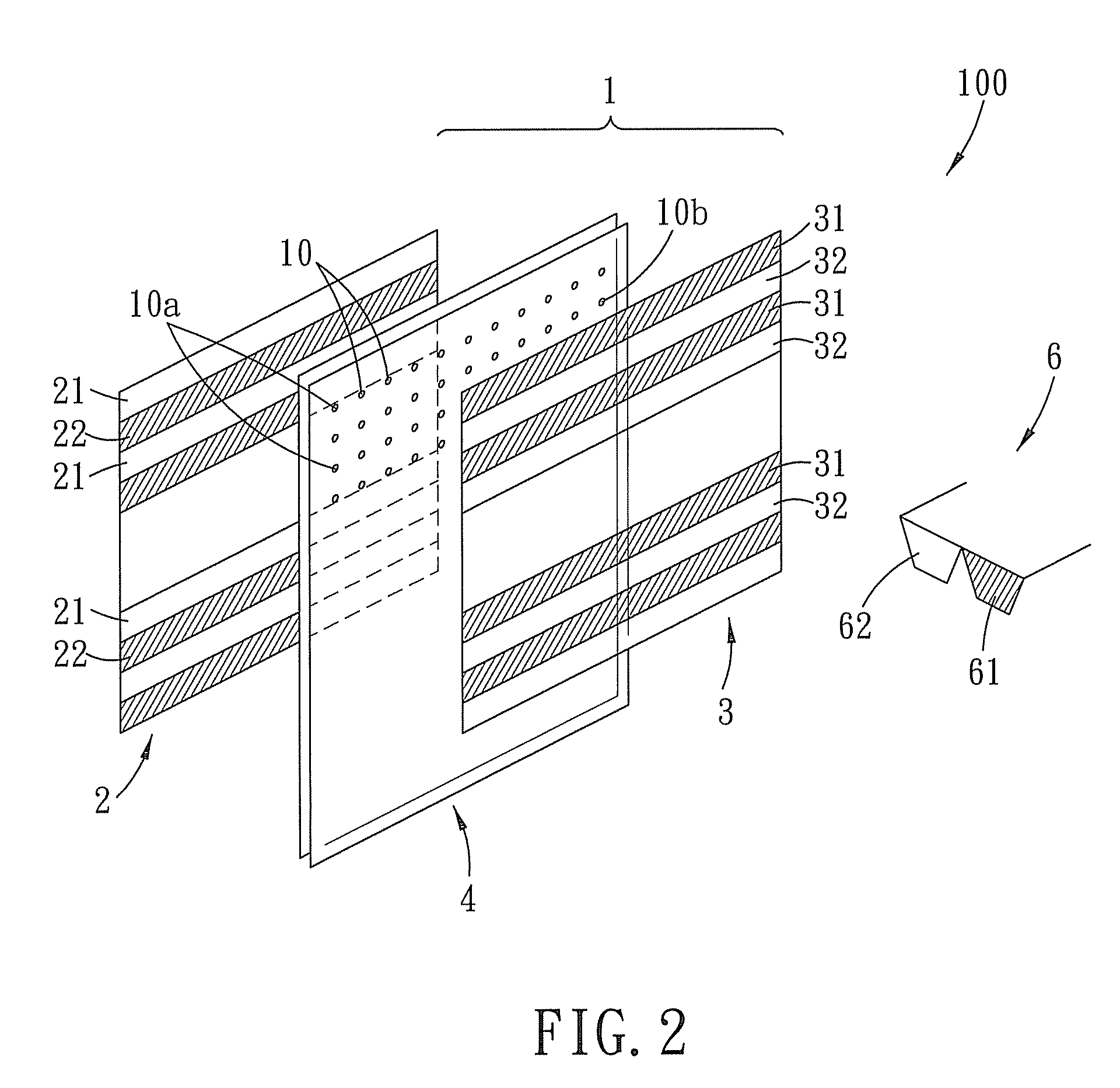
[0031]FIG. 2 schematically illustrates a stereoscopic display system 100 according to the invention. The stereoscopic display system 100 includes a stereoscopic display device 1 and stereoscopic glasses 6. The stereoscopic display device 1 is depicted in detail in FIG. 3, and includes a backlight module 5 for emitting a light beam, an inner polarizer 2 disposed proximate to the backlight module 5 for receiving the light beam emitted by the backlight module 5, an outer polarizer 3 spaced apart from the inner polarizer 2, and a display substrate panel 4 interposed between the inner and outer polarizers 2, 3. The display substrate panel 4 is a component currently used in a conventional liquid crystal display, and includes, arranged in sequence from the outside to the inside, a pair of glass substrates 41 having pix...


PUM

PropertyMeasurementUnit
polarization angleaaaaaaaaaa
coloraaaaaaaaaa

Abstract

A stereoscopic display device includes an inner polarizer, an outer polarizer, and a display substrate panel interposed between the inner and outer polarizers. The inner polarizer has first and second polarization regions arranged alternately and having a 90-degree polarization angle difference. The outer polarizer has third and fourth polarization regions corresponding in position to the first and second polarization regions. The third and first polarization regions have a 90-degree polarization angle difference. The fourth and second polarization regions have a 90-degree polarization angle difference. Light passing through the first polarization regions, the display substrate panel, and the third polarization regions can pass through one lens of a pair of stereoscopic glasses, whereas light passing through the second polarization regions, the display substrate panel, and the fourth polarization regions can pass through the other lens of the stereoscopic glasses.

Description

CROSS-REFERENCE TO RELATED APPLICATION[0001]This application claims priority of Taiwanese Application No. 097135795, filed on Sep. 18, 2008.BACKGROUND OF THE INVENTION[0002]1. Field of the Invention[0003]The invention relates to a stereoscopic display technique for a liquid crystal display device, more particularly to a stereoscopic display technique that can be used to produce stereoscopic effects by modifying polarizers of a liquid crystal display device.[0004]2. Description of the Related Art[0005]In order to enable a flat screen to present a stereoscopic effect, the principle of stereoscopic vision has to be employed. In other words, an image intended to be seen with the left eye should be transmitted to the left eye, and an image intended to be seen with the right eye should be transmitted to the right eye so that, after processing by the brain, stereoscopic images will be formed in the brain.[0006]For three-dimensional motion pictures, they can be produced using the principle ...

Claims


Application Information

Patent Timeline
Patent Type & Authority Patents(United States)
IPC IPC(8): G02F1/133G02B30/25
CPCG02B27/26H04N13/0434H04N13/0486H04N13/0497G02F1/1323G02F1/133615G02F2001/133531G02F2001/133538H04N13/337H04N13/315H04N13/398G02B30/25G02F1/133538G02F1/133531
Inventor CHANG, YAO-TSUNG
Owner WISTRON CORP
Why Eureka
Try Eureka