Universal multimodal transportation system and associated infrastructure

a multimodal transportation and infrastructure technology, applied in the field of transportation systems, can solve the problems of affecting both vehicle control and traction, unable to meet the requirements of skill and/or attention,

Inactive Publication Date: 2015-08-04
WFK & ASSOC
View PDF25 Cites 10 Cited by
  • Summary
  • Abstract
  • Description
  • Claims
  • Application Information

AI Technical Summary

Benefits of technology

[0015]Still yet a further advantage is realized by creating a rail structure wherein the contact surface for wheeled vehicles is minimized.

Problems solved by technology

Moreover, anyone lacking the requisite skill and / or attention can suffer dire and fatal consequences.
Conventional highways are also vulnerable to weather conditions such as ice, rain, snow, grease, hydroplaning, silt, mud, strong winds, lightning, fog, and smog visibility, all of which affect both vehicle control and traction.
Night conditions, visibility and lightning can add to the difficulty of the driver.
Conventional highways are also required to be much wider than the vehicle because even skilled drivers cannot steer the vehicle along a precise path.
Vehicles traveling upon conventional highways are also prone to accidents that result in the vehicle running off of the highway, hitting stationary objects, rolling over, going into water, or traveling down embankments.
Vehicles can likewise be involved in collisions with other vehicles.
Furthermore, because highways are typically built on the surface or on grade, both the highway and the vehicles traveling thereon present a hazard to children, pedestrians, pets, wildlife, and bicycles.
Highways are also undesirable because they require a broad finished asphalt or concrete surface even though the wheels of vehicles actually use only a fraction of this surface.
This creates a large heat sink and results in undesirable water run off.
The areas above and below our highways are often crowded.
When services go into the ground they become less accessible, harder to find, create interference with one another and are subject to more corrosive forces.
When services go overhead they create clutter and the wooden or concrete supporting poles are a hazard.
There is also the disadvantage that with all the problems of vehicle control, potential mechanical failures, highway conditions and the limitations of human operators the vehicles cannot safely travel at speeds up to the aerodynamic and physical potential of the vehicle.

Method used


Image

  • Universal multimodal transportation system and associated infrastructure
  • Universal multimodal transportation system and associated infrastructure
  • Universal multimodal transportation system and associated infrastructure

Examples


Embodiment Construction

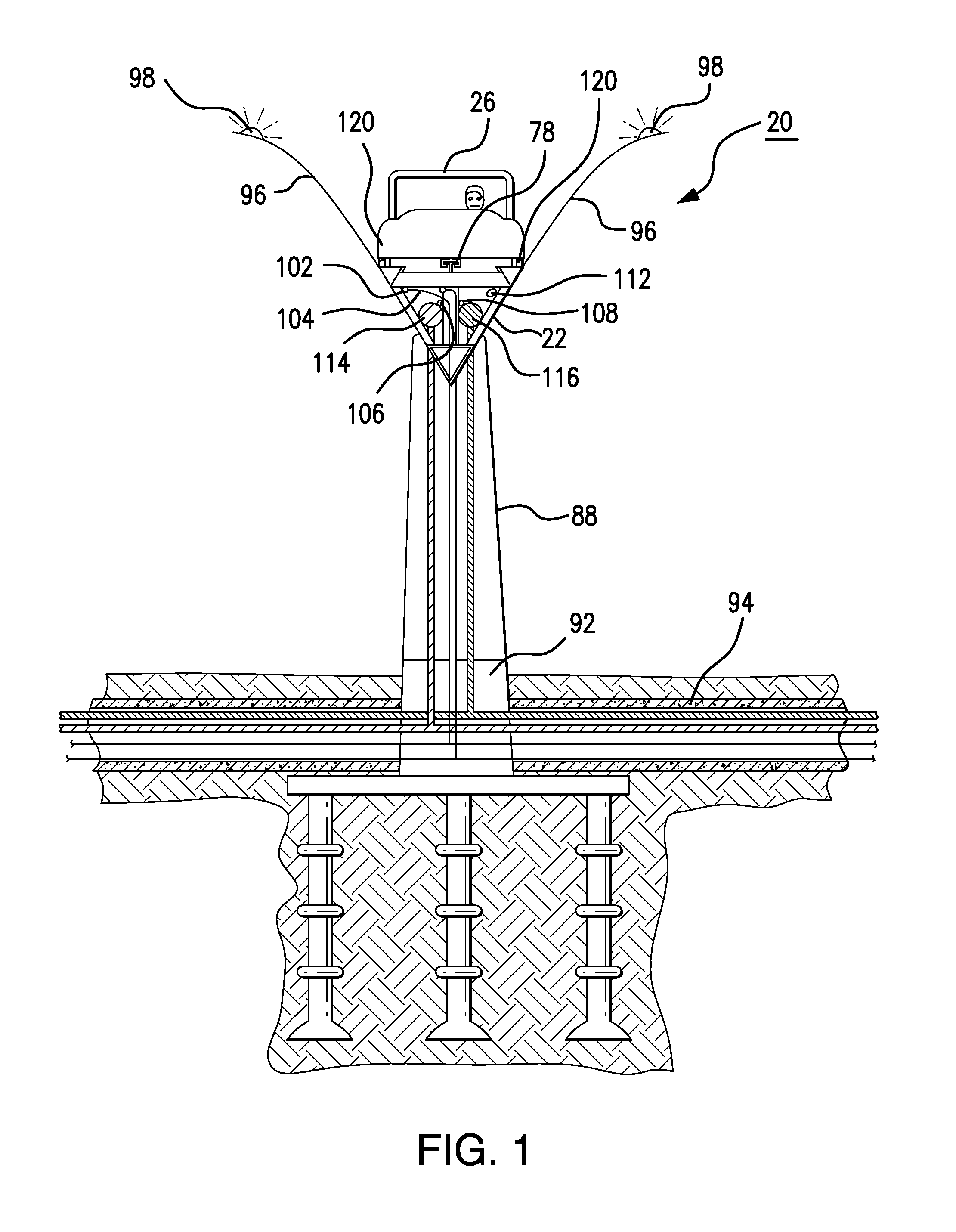
[0033]The present invention relates to a transportation system 20 that provides a universal infrastructure. In one embodiment, the infrastructure 20 takes the form of a hollow elevated load bearing guideway structure 24 designed to support the weight of traveling vehicles. Structure 24 supports a universal control beam 46 that has multiple functions. These functions may include several forms of vehicle control, security, and energy delivery. Structure 24 supports bimodal wheels 120 (FIG. 9-17). The bimodal wheel 120 has a flat surfaced cylindrical side 134 which functions similar to automotive wheels and steel rimmed surfaces 158, 138, 132, 124 which function similar to the wheels on a train. However, there is not a direct equivalence. A bimodal wheel 120 uses all of these characteristics while traveling on the universal infrastructure. The various components of the present invention, and the manner in which they interrelate, are described in greater detail hereinafter.

Elevated Guid...


PUM


Abstract

Disclosed is a transportation system with integrated infrastructure. In one embodiment, this infrastructure takes the form of a hollow elevated load bearing guideway structure designed to support the weight of traveling vehicles. The structure supports a backbone beam, or rail, that has multiple functions. These functions may include vehicle control, security, and energy delivery. The structure is bimodal meaning vehicles can have wheels like cars or steel rimmed wheels like a train or any combination thereof.

Description

CROSS REFERENCE TO RELATED APPLICATIONS[0001]This application claim priority to, and is a continuation-in-part of, co-pending Utility patent application Ser. No. 12 / 827,437 entitled “Integrated Multimodal Transportation System and Associated Infrastructure,” which was filed on Jun. 30, 2010. That application, in turn, claims priority to Provisional Patent Application No. 61 / 221,669 filed on Jun. 30, 2009 and entitled “Automated Guideway Infrastructure.” The contents of both these applications are fully incorporated herein.BACKGROUND OF THE INVENTION[0002]1. Field of the Invention[0003]The present invention relates to a transportation system. More specifically, the present invention relates to a transportation system with integrated infrastructure and multi-modal transport vehicles.[0004]2. Description of the Background Art[0005]Most everyone is familiar with transportation infrastructure such as the highways, streets, roads and limited access Interstates. Although widely used, such ...

Claims


Application Information

Patent Timeline
Patent Type & Authority Patents(United States)
IPC IPC(8): B61B5/02B60F1/02B61B15/00B61B13/04E01B25/08
CPCB61B5/02B61B13/04E01B25/08B60F1/02B61B15/00Y02T30/30Y02T30/40Y02T30/00B61L23/14B61L25/02E01B25/28
Inventor KISSEL, WALDEMAR F.
Owner WFK & ASSOC
Why Eureka
Try Eureka