
Surgical fluid management systems and methods

a fluid management system and surgical technology, applied in the field of surgical fluid management systems and methods, can solve the problems of large diameter, serious complications and even death, and significant risk of distending fluid being taken up by a cut blood vessel

Active Publication Date: 2015-07-21
BOSTON SCI SCIMED INC
View PDF30 Cites 15 Cited by
  • Summary
  • Abstract
  • Description
  • Claims
  • Application Information

AI Technical Summary

Benefits of technology

[0017]In a fifth aspect of the present invention, the medical fluid management system comprises a filter including both a first tissue-capture filter and a second hollow fiber filter. The first fluid line is configured to carry distention fluid from a fluid source to a body space. Second and third fluid lines are configured to recirculate fluid from the body space through the filter assembly and back to the fluid source. At least one check valve will be positioned intermediate the first and second filters to prevent backflow of fluid from the hollow fiber filter to the first filter. In specific embodiments, the system will comprise a fourth fluid line joining the first tissue-capture filter and the second hollow fiber filter, where the check valve is present in the fourth line. In further specific aspects, the first filter is configured for de-coupling from the system to allow removal of cut tissue. The first filter is also preferably configured to allow transport of the cut tissue after the filter has been decoupled from the system. In still further specific aspects, at least one additional check valve may be provided in the second fluid line to prevent backflow of fluid from the first filter to the body and a further additional check valve may be provided in the first fluid line for preventing backflow of fluid from the body to the fluid source.

Problems solved by technology

One particular concern is the fact that fluid management systems typically administer the fluid under a pressure of up to 100 mm Hg or more which results in a significant risk that the distending fluid may be taken up by a cut blood vessel exposed in the uterine cavity.
Such unwanted fluid uptake is known as intravasation, which can lead to serious complications and even death.
While hysteroscopic resection can be effective in removing uterine fibroids, many commercially available instrument are too large in diameter and thus require anesthesia in an operating room environment.

Method used


Image

  • Surgical fluid management systems and methods
  • Surgical fluid management systems and methods
  • Surgical fluid management systems and methods

Examples


Embodiment Construction

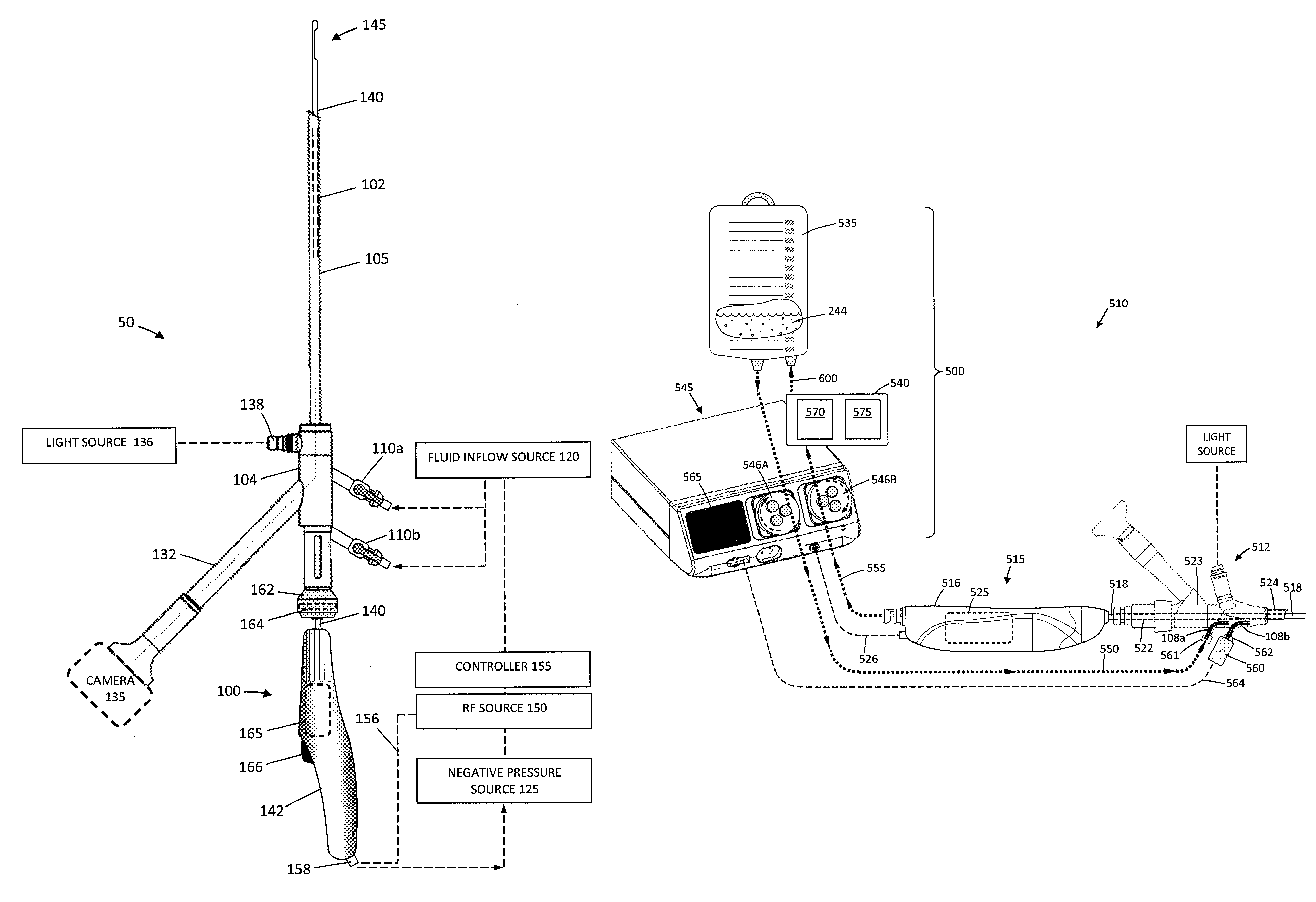
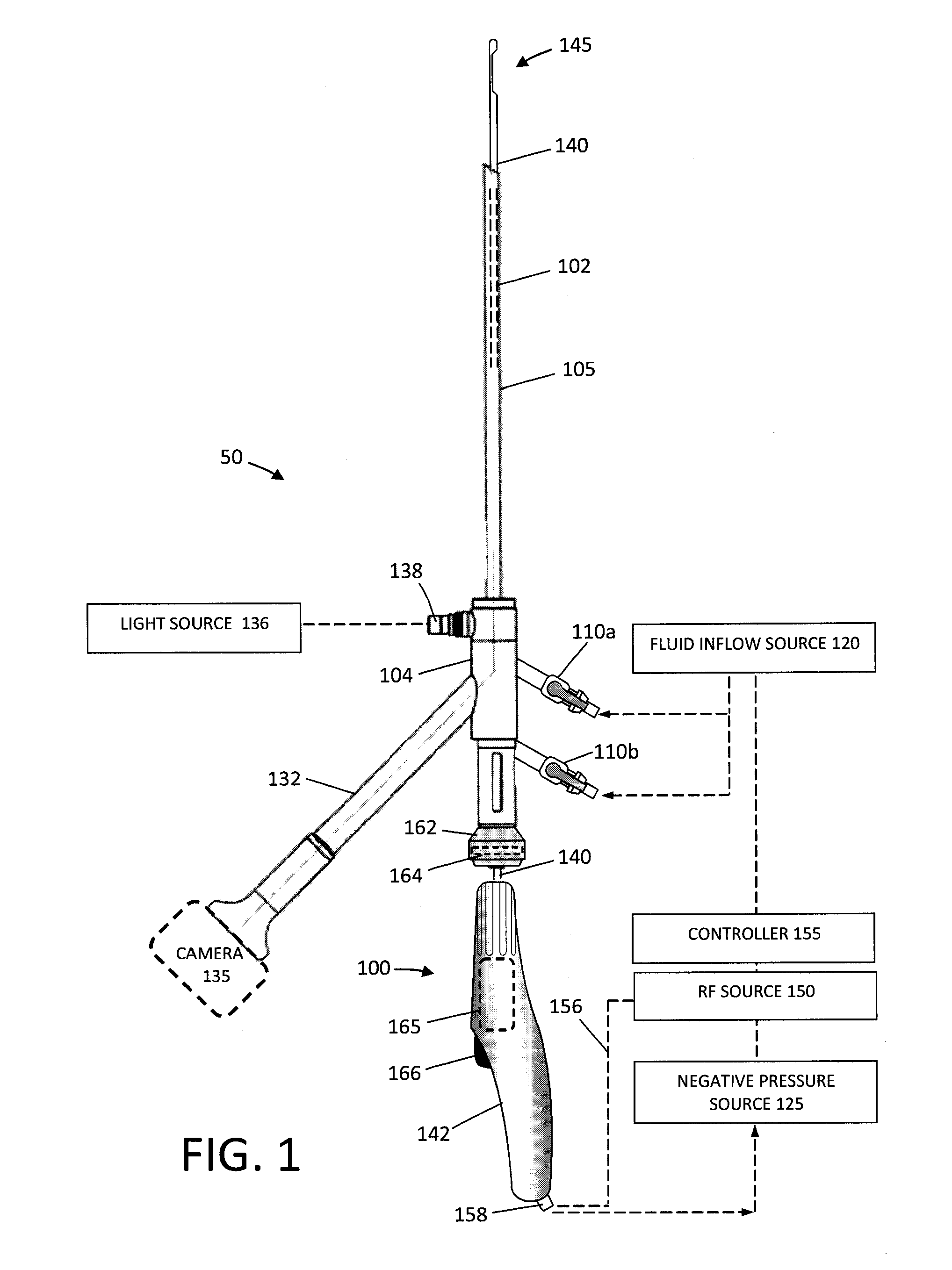
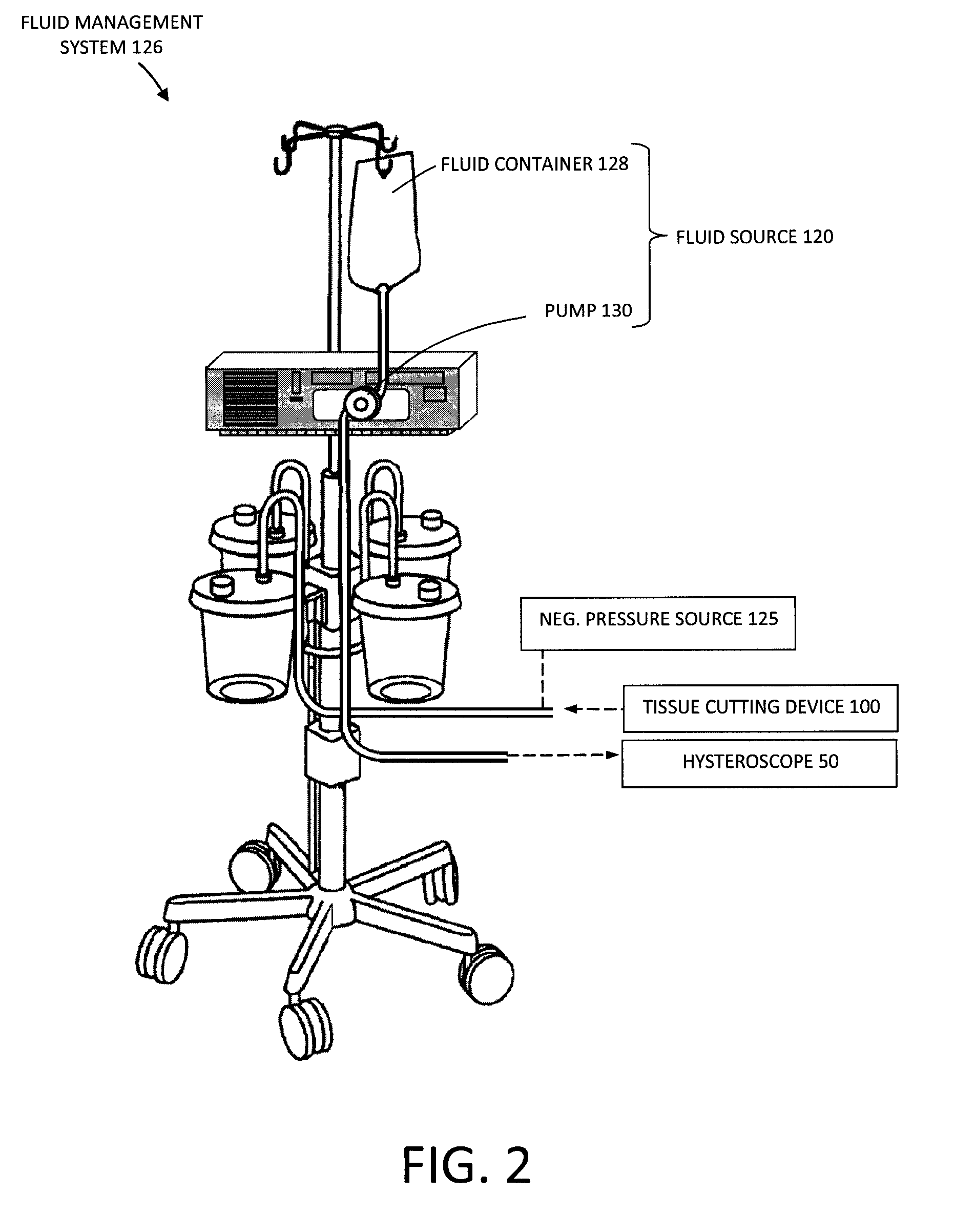
[0045]FIG. 1 illustrates an assembly that comprises an endoscope 50 used for hysteroscopy together with a tissue-extraction device 100 extending through a working channel 102 of the endoscope. The endoscope or hysteroscope 50 has a handle 104 coupled to an elongated shaft 105 having a diameter of 5 mm to 7 mm. The working channel 102 therein may be round, D-shaped or any other suitable shape. The endoscope shaft 105 is further configured with an optics channel 106 and one or more fluid inflow / outflow channels 108a, 108b (FIG. 3) that communicate with valve-connectors 110a, 110b configured for coupling to a fluid inflow source 120 thereto, or optionally a negative pressure source 125 (FIGS. 1-2). The fluid inflow source 120 is a component of a fluid management system 126 as is known in the art (FIG. 2) which comprises a fluid container 128 and pump mechanism 130 which pumps fluid through the hysteroscope 50 into the uterine cavity. As can be seen in FIG. 2, the fluid management syste...


PUM


Abstract

A surgical fluid management system delivers fluid for distending a uterine cavity to allow cutting and extraction of uterine fibroid tissue, polyps and other abnormal uterine tissue. The system comprises a fluid source, fluid deliver lines, one or more pumps, and a filter for re-circulating the distension fluid between the source and the uterine cavity. A controller can monitor fluid retention by the patient.

Description

CROSS REFERENCE TO RELATED APPLICATIONS[0001]The present application claims priority to Provisional Application No. 61 / 538,034, filed Sep. 22, 2011; Provisional Application No. 61 / 539,865, filed Sep. 27, 2011; and Provisional Application No. 61 / 597,000, filed Feb. 9, 2012, the entire contents of which are incorporated herein by reference in their entirety.FIELD OF THE INVENTION[0002]The present invention relates surgical fluid management systems and methods, for example for use in distending the uterine cavity to allow cutting and extraction of uterine fibroid tissue, polyps and other abnormal uterine tissue.BACKGROUND OF THE INVENTION[0003]Uterine fibroids are non-cancerous tumors that develop in the wall of uterus. Such fibroids occur in a large percentage of the female population, with some studies indicating up to 40 percent of all women have fibroids. Uterine fibroids can grow over time to be several centimeters in diameter and symptoms can include menorrhagia, reproductive dys...

Claims


Application Information

Patent Timeline
Patent Type & Authority Patents(United States)
IPC IPC(8): A61M1/00A61B17/32A61B18/14A61B18/12A61B18/00A61B18/16A61B17/42A61B19/00
CPCA61M1/0064A61B17/32A61B17/32002A61B18/1485A61M1/006A61B2017/4216A61B2018/00559A61B2018/00601A61B2018/00625A61B2018/1213A61B2018/162A61B2019/464A61B2217/007A61B1/012A61B1/303A61M3/0229A61M2205/3344A61M2210/1433A61M2205/7545A61B2090/064A61M3/022A61M3/0212A61M3/0208A61M1/777A61M1/79A61M1/774A61M3/0266A61M2202/0021A61M2202/0028A61M2205/75A61B2217/005
Inventor KLEIN, KYLEGERMAIN, AARONTRUCKAI, CSABAWALKER, MICHAEL D.
Owner BOSTON SCI SCIMED INC
Learn More