Ophthalmologic photography apparatus

a technology for ophthalmologic photography and equipment, applied in the field of ophthalmologic photography equipment, can solve the problems of preventing the realization of compact and inexpensive ophthalmologic photography equipmen

Inactive Publication Date: 2015-07-07
KOWA CO LTD
View PDF16 Cites 0 Cited by
  • Summary
  • Abstract
  • Description
  • Claims
  • Application Information

AI Technical Summary

Benefits of technology

[0017]In the present invention, a pair of right and left ocular fundus images having a parallax formed as temporary intermediate images is separated into the right and left by optical path splitting lenses and re-formed on the imaging plane of the imaging means. This advantageously allows two ocular fundus images for three-dimensional viewing to be produced without using an optical path splitting prism, thus providing a compact, simply structured stereoscopic ophthalmologic photography apparatus.

Problems solved by technology

The ophthalmologic photography apparatuses proposed in Patent Documents Nos. 1 and 2 have disadvantages in that each of the right and left images having a parallax must be formed independently, and the right and left optical paths must be transposed using an optical path splitting prism in order to observe the images with both eyes or to photograph the images using an imaging element.
This necessitates prisms at many locations, and therefore the apparatus is large by necessity, preventing the realization of a compact and inexpensive ophthalmologic photography apparatus.

Method used


Image

  • Ophthalmologic photography apparatus
  • Ophthalmologic photography apparatus
  • Ophthalmologic photography apparatus

Examples


embodiments

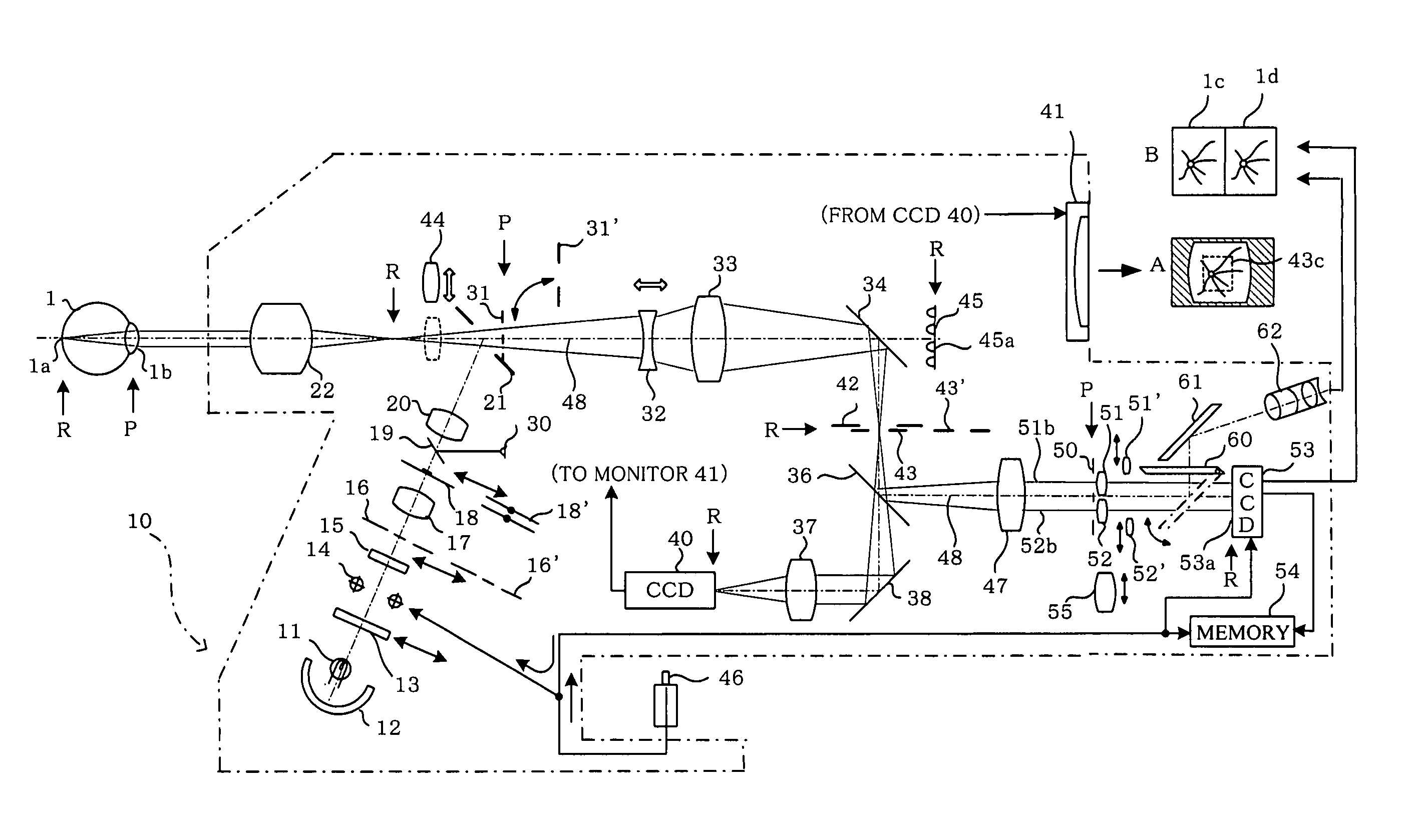
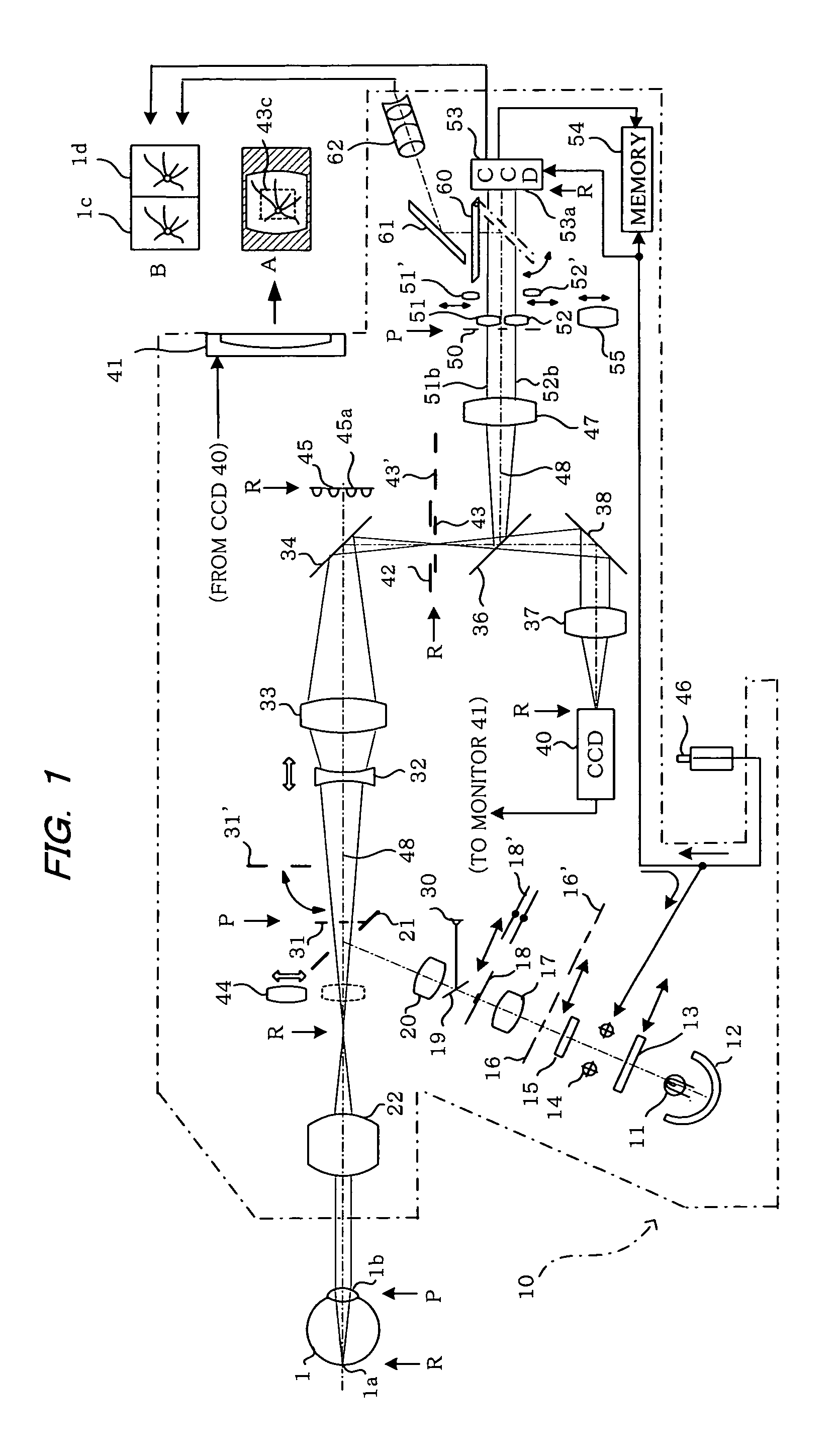
[0033]FIG. 1 shows a fundus camera 10 capable of stereoscopic photography (three-dimensional photography) and monocular photography. The illustration in FIG. 1 is primarily that of stereoscopic photography, and a switch to each corresponding optical element can be made when monocular photography is performed.

[0034]The fundus camera 10 is provided with an illumination optical system for illuminating the ocular fundus, and an optical system for forming an image of the illuminated ocular fundus. In the illumination optical system, light emitted from a light source 11 such as a halogen lamp and light reflected by a concave mirror 12 are converted into infrared light via a visible-blocking / infrared-transmitting filter 13 that can be inserted into and withdrawn from the optical path. The infrared light is transmitted through a strobe 14 and diffused by a diffusion plate 15 to illuminate a ring slit 16 for stereoscopic photography that is disposed in a position conjugate with an anterior o...


PUM


Abstract

A light beam reflected from an ocular fundus is split into a pair of right and left light beams by a two-aperture stop disposed in a position conjugate with an anterior ocular segment of an eye to be examined. The pair of right and left ocular fundus images having a parallax is formed as intermediate images from the split light beams at the position of a photographic mask. The optical path of the pair of ocular fundus images formed as intermediate images is split by a pair of optical path splitting lenses disposed in a position substantially conjugate with the two-aperture stop. One ocular fundus image is re-formed on half of an imaging plane of an imaging element, and the other ocular fundus image is reformed separately on the other half of the imaging plane. With such a structure, two ocular fundus images for three dimensional viewing can be efficiently obtained without using a prism for splitting the optical path.

Description

CROSS-REFERENCE TO RELATED APPLICATIONS[0001]This application is a U.S. national stage application of International Application No. PCT / JP2009 / 064823 filed Aug. 26, 2009, claiming a priority date of Jan. 30, 2009, and published in a non-English language.TECHNICAL FIELD[0002]The present invention relates to an ophthalmologic photography apparatus, and more specifically to an ophthalmologic photography apparatus such as a fundus camera capable of observing and photographing a pair of ocular fundus images having a parallax for three-dimensional viewing.BACKGROUND ART[0003]Conventionally, fundus cameras are known in which light that is incident on an ocular fundus via an objective lens and reflected therefrom is split to provide split light beams which are formed into images by a pair of image-forming optical systems to observe and photograph a pair of right and left ocular fundus images for three-dimensional viewing (Patent Documents Nos. 1 and 2).[0004]There are also ophthalmologic ph...

Claims


Application Information

Patent Timeline
Patent Type & Authority Patents(United States)
IPC IPC(8): H04N13/02A61B3/13A61B3/12A61B3/14
CPCA61B3/12A61B3/132G06T2207/30041G06T2207/10012A61B3/14
Inventor SUZUKI, TAKAYOSHI
Owner KOWA CO LTD
Why Eureka
Try Eureka