Portable work apparatus having straps

a technology of work equipment and straps, which is applied in the direction of mechanical equipment, buckles, agriculture tools and machines, etc., can solve the problems of time-consuming and time-consuming correction of changes in position, and the frequency of unintended changes in the position of straps relative to the main uni

Active Publication Date: 2015-07-07
ANDREAS STIHL AG & CO KG
View PDF17 Cites 1 Cited by
  • Summary
  • Abstract
  • Description
  • Claims
  • Application Information

AI Technical Summary

Benefits of technology

[0008]The portable work apparatus of the invention includes: a strap having at least one fastening section; a main unit configured to be carried by an operator via the strap; a fastening surface incorporated in the main unit; a work tool; a fastening element having a pressure surface; the strap being configured fixed to the main unit via the fastening element in such a manner that the fastening section of the strap is held between the pressure surface of the fastening element and the fastening surface of the main unit; the fastening section of the strap having a bearing surface which faces the fastening surface; the fastening section of the strap being configured to be held clamped between the pressure surface of the fastening element and the fastening surface of the main unit in a clamped position; and, the fastening surface having a friction increasing structure formed thereon to coact with the bearing surface of the fastening section in such a manner that a rotational movement of the fastening section relative to the main unit is prevented when the fastening section is clamped into the clamped position.
[0009]A fastening section of the strap to be secured to the main body is held between a pressure surface of a fastening element and a fastening surface formed on the main unit. The fastening surface is formed with a structure that increases the friction coefficient. The fastening section of the strap has a bearing surface which faces the fastening surface formed on the main unit. The structure coacts with the bearing surface of the fastening section of the strap such that a rotational movement of the fastening section and thus of the strap relative to the main unit is prevented.
[0010]As a result of the friction coefficient increasing structure, it is ensured that the fastening section, arranged on the main unit in an oriented position, of the strap cannot slip in an arbitrary fashion relative to the main unit because the structure of the fastening surface and the strap enter into operative connection with one another. If, for example, a fastening section of the strap is secured by screws, the structure engaging into the material of the fastening section of the strap prevents the fastening section of the strap being carried along in the screwing direction of the fastening element, and so the orientation of the strap does not change during securing and corrections to the strap position can be dispensed with.
[0011]The structure increases the bearing surface area of the fastening section on the main unit. As a result, the force distribution is improved.
[0014]In an embodiment of the invention, the free end of an individual, preferably cylindrical elevation is formed in a pointed manner, such that an elevation has an approximately conical or thorn-like shape. This three-dimensional shape of an elevation ensures easy penetration into the material of the strap, so that as a result of simple holding of the strap during mounting, initial engagement between the structure and the material of the strap is already achieved. The conical, thorn-like configuration of an elevation furthermore has the advantage that the elevation itself is mechanically stable and, in the case of a strap consisting of fabric, the elevations pass between the warp and weft threads, that is, merely displace and do not destroy the threads of the fabric.
[0018]In order to keep the driving forces that act on the fastening section of the strap during securing as low as possible when the fastening element is being mounted, provision is made for the pressure surface of the fastening element to be formed in a smooth manner, in particular a planar manner. As a result, low friction is ensured between the fastening element and the strap.

Problems solved by technology

When the strap is fastened to the main unit, the strap is intended to be secured in an orientation required for subsequent use; when the strap is screwed to a back panel of the main unit, unintended changes in position of the strap relative to the main unit frequently occur in practice.
These changes in position have to be corrected in a time-consuming manner.

Method used


Image

  • Portable work apparatus having straps
  • Portable work apparatus having straps
  • Portable work apparatus having straps

Examples


Embodiment Construction

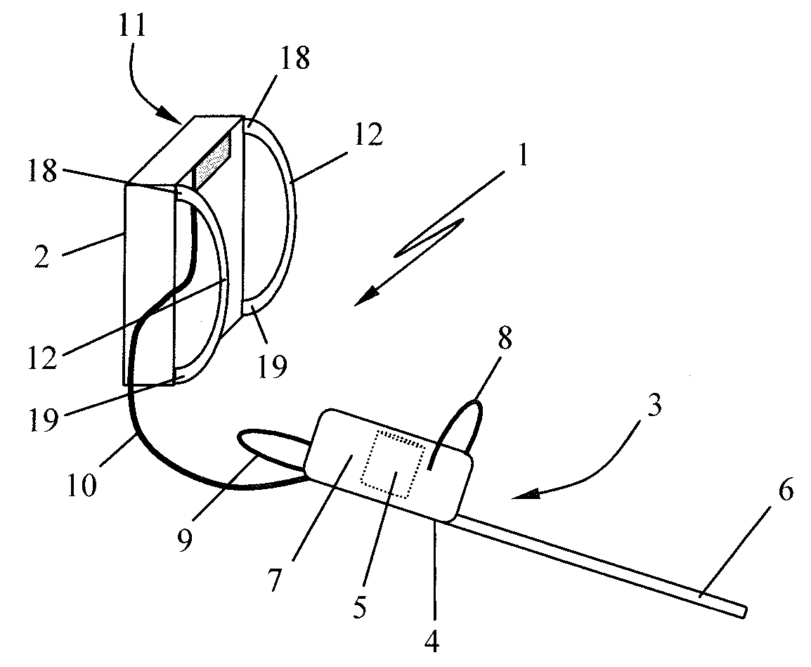
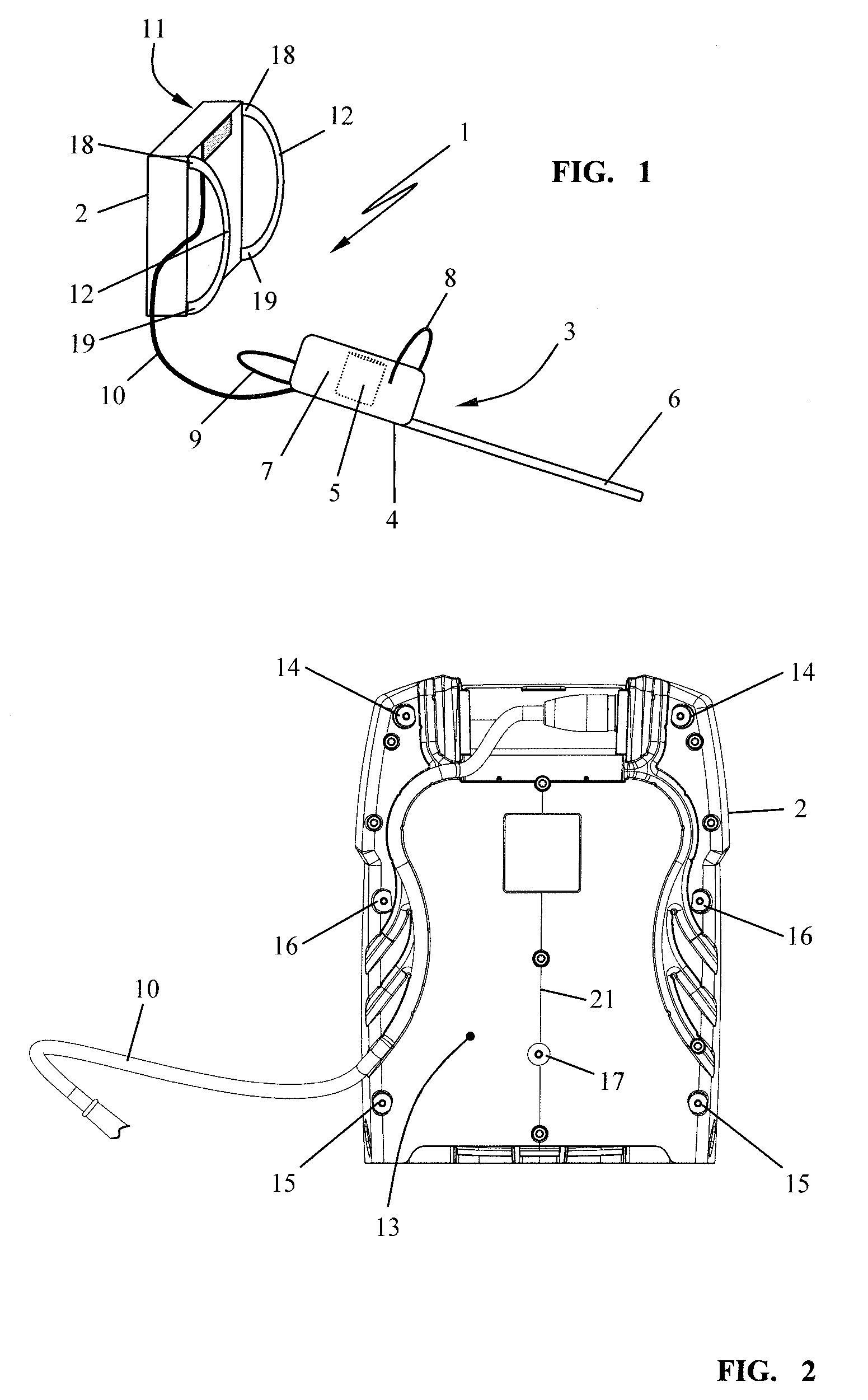
[0036]The work apparatus 1 shown in the exemplary embodiment substantially includes a main unit 2 and a work tool 3. In the embodiment shown, the work apparatus 1 is an electric hedge trimmer 4 having an electric drive motor 5 which is arranged at one end of a cutter bar 6. The cutter bar includes two reciprocating blades. The drive motor 5 is mounted in a housing 7 which has a front handle 8 and a rear handle 9 for holding and guiding the portable work tool 3. The work tool 3 guided by the user is connected to the main unit 2 via a flexible connection 10. In the case of the portable, electric work apparatus 1 shown in FIG. 1, the flexible connection 10 includes a flexible electrical cable which connects the battery packs, for example lithium-ion battery packs, accommodated in the main unit 2 to the electric drive motor 5 as electrical consumer.

[0037]The main unit 2 equipped with battery packs thus serves for supplying energy to the electric drive motor 5, wherein the main unit 2 is...


PUM


Abstract

A portable work apparatus has a main unit and a work tool. The main unit is carried by the user via a strap. The strap has a fastening section which is secured to the main unit via a fastening element. The fastening section is held between a pressure surface of the fastening element and a fastening surface formed on the main unit. To prevent twisting of the strap when the fastening element is secured, provision is made for the fastening surface to be formed with a structure that increases the friction coefficient. The structure interacts with a bearing surface, facing the fastening surface, of the fastening section such that the fastening section, which is held in a clamped manner between the pressure surface of the fastening element and the fastening surface of the main unit, is prevented from rotating relative to the main unit.

Description

CROSS REFERENCE TO RELATED APPLICATION[0001]This application claims priority of German patent application no. 10 2012 021 000.0, filed Oct. 26, 2012, the entire content of which is incorporated herein by reference.FIELD OF THE INVENTION[0002]The invention relates to a portable work apparatus which includes a main unit, carried by the user at least via a strap, and a work tool.BACKGROUND OF THE INVENTION[0003]U.S. Pat. No. 7,309,028 discloses a backpack-type blowing apparatus, the main unit of which is intended to be carried on the back of a user via straps. The work tool is formed by the blower tube, which is connected via a flexible connection to the work apparatus carried on the back and is guided by the user.[0004]DE 196 16 764 C2 discloses a further work apparatus which includes a drive unit carried on the back and a work tool connected to the drive unit via a flexible shaft. The drive unit is carried as main unit on the back of a user, for which purpose the main unit is provide...

Claims


Application Information

Patent Timeline
Patent Type & Authority Patents(United States)
IPC IPC(8): A44B11/00A01D34/90F16B2/00B05B7/14A01G3/053A45F3/14
CPCA44B11/00A01D34/902Y10T24/47F16B2/005B05B7/1413A01G3/053A45F2003/146
Inventor KOLB, JOACHIMREBER, VOLKERMAIER, ALEXANDER
Owner ANDREAS STIHL AG & CO KG
Why Eureka
Try Eureka