
Pressure-measuring plug for a combustion engine

a technology for combustion engines and pressure-measuring plugs, which is applied in the direction of machines/engines, mechanical equipment, instruments, etc., can solve the problems of high pressure release rate, inability to use pressure-measuring plugs, and require fast and accurate pressure response, etc., to achieve long-lasting and cheaper manufacturing

Active Publication Date: 2015-06-23
SENSATA TECHNOLOGIES INC
View PDF12 Cites 5 Cited by
  • Summary
  • Abstract
  • Description
  • Claims
  • Application Information

AI Technical Summary

Benefits of technology

The present invention provides an improved pressure-measuring plug for receiving a rod-shaped element in the through hole of the sensing structure. The plug has reliable and durable components that can be easily assembled and disassembled, making it useful in a variety of applications such as spark plugs, temperature sensors, and glow plugs. The plug structure allows for easy replacement of malfunctioning components without having to replace the whole component, which saves time and money. The plug is also designed to reduce hysteresis and stress while still providing accurate pressure readings. Additionally, the plug can be easily combined with different types of spark plugs or functions, making it more versatile and cost-effective. The plug design also allows for a sealing profile to provide a robust sealing of the gasses in the combustion chamber. The predefined distance between the annular membrane and the distal end of the plug body provides the optimal operating temperature for the plug.

Problems solved by technology

These strategies may or may not include Homogeneous Charge Compression Ignition (HCCI) combustion, and can result in high pressure release rates which require fast and accurate pressure response.
However, the pressure-measuring plug is not used for mounting in a cylinder head of a combustion engine.
As the sensing structure is integrated in the plug body, the dimension of the hole in the sensing structure is limited.
Until now, spark plugs incorporating a pressure sensor have suffered from hysteresis, lack of sealing and sensitivity to external influences such as temperature.

Method used


Image

  • Pressure-measuring plug for a combustion engine
  • Pressure-measuring plug for a combustion engine
  • Pressure-measuring plug for a combustion engine

Examples


Embodiment Construction

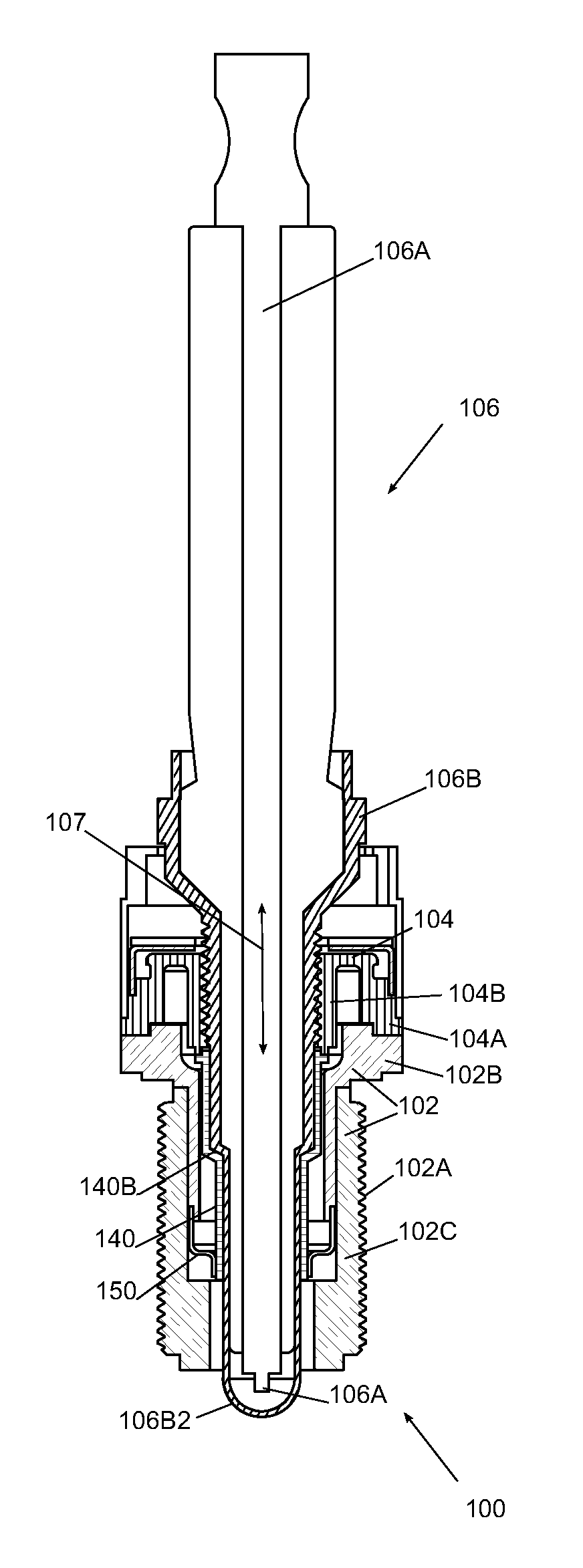
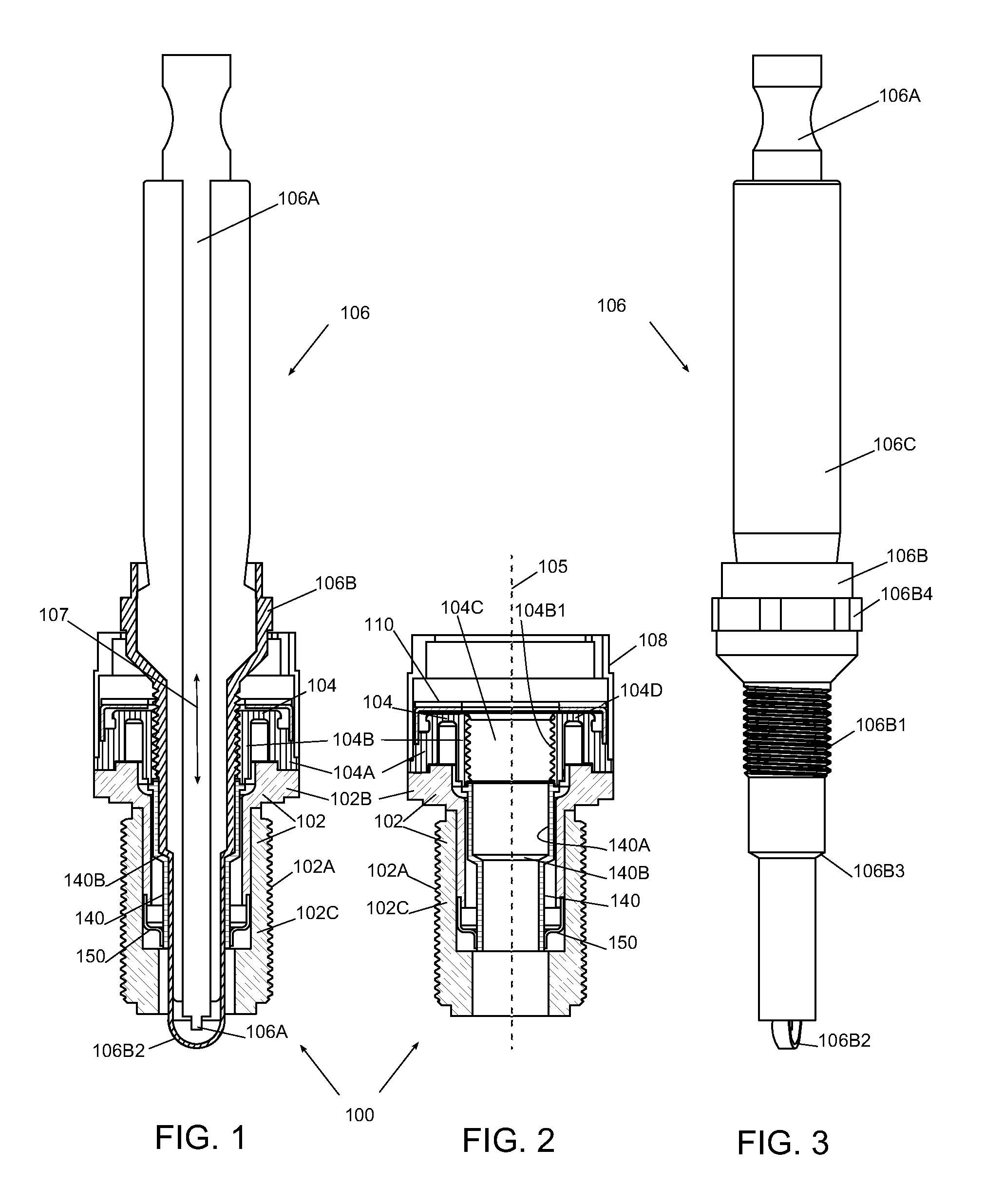
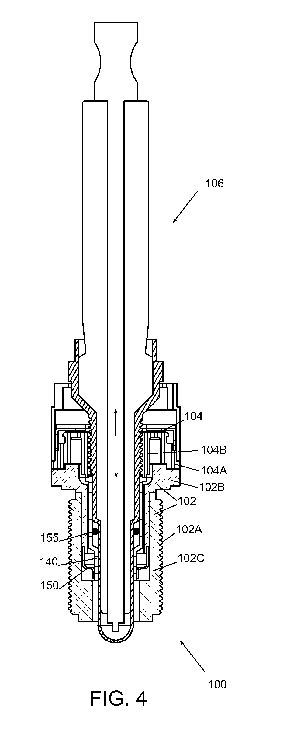
[0026]FIGS. 1 and 2 show schematically a sectional view of a first embodiment of a pressure-measuring plug 100 for a combustion engine. The pressure-measuring plug 100 comprises a plug body 102 and a ring-shaped sensing structure 104. A spark plug 106 is removably positioned in the pressure-measuring plug 100. The pressure-measuring plug 100 further comprises a housing 108 which is provided with a hexagonal periphery to enable the mounting of the pressure-measuring device with a wrench.

[0027]The plug body 102 comprises an external thread 102A for mounting the plug body 102 into a cylinder head of a combustion engine. The plug body 102 comprises a base part 102B and a threaded part 102C which comprises the external thread. A part of the base part 102B extends in the through hole of the threaded body part 102C.

[0028]The ring-shaped sensing structure 104 comprises an outer section 104A, an inner core 104B and a diaphragm 104D. The diaphragm 104D connects movably the inner core 104B to ...


PUM

PropertyMeasurementUnit
pressureaaaaaaaaaa
temperatureaaaaaaaaaa
displacementaaaaaaaaaa

Abstract

Disclosed is a pressure-measuring plug for a combustion engine. The pressure-measuring plug comprises a plug body and a ring-shaped sensing structure. The plug body comprises an external thread for mounting the plug body into a cylinder head of the combustion engine. The ring-shaped sensing structure comprises an outer section and an inner core. A proximal end of the plug body is attached to the outer section. The inner core comprises a through hole for receiving a rod-shaped element. The ring-shaped sensing structure allows the inner core to move relatively to the outer section along a cylinder axis of the ring-shaped sensing structure. The inner core further comprises an internal thread for mounting in the through hole a rod-shaped element with an external thread.

Description

TECHNICAL FIELD[0001]The invention relates to a pressure-measuring plug for a combustion engine with a plug body comprising an external thread for mounting the plug body into a cylinder head of the combustion engine and a ring-shaped sensing structure comprising a through hole for receiving a rod-shaped element. The ring-shaped sensing structure allows the inner core to move relatively to the outer section along a cylinder axis of the ring-shaped sensing structure. More particularly, the invention relates to a piezo-resistive pressure-measuring plug for a combustion engine.BACKGROUND ART[0002]Advanced combustion strategies for gasoline engines in the future depend on the existence of accurate pressure feedback from each combustion cylinder during the entire cycle (compression-combustion-exhaust cycle). These strategies may or may not include Homogeneous Charge Compression Ignition (HCCI) combustion, and can result in high pressure release rates which require fast and accurate pressu...

Claims


Application Information

Patent Timeline
Patent Type & Authority Patents(United States)
IPC IPC(8): G01M15/08G01L23/18F02B77/08
CPCG01M15/08G01L23/18Y10T29/4973F02B77/085F02P13/00G01L23/08G01L23/26
Inventor ZWOLLO, CRIS RUISGROENHUIJZEN, SERGEBORGERS, MARC
Owner SENSATA TECHNOLOGIES INC
Learn More