
Device and method for assembling an electronic device and a flexible element for facilitating assembly of electronic components

a technology of electronic components and devices, applied in the direction of coupling device connections, electrical apparatus casings/cabinets/drawers, catheters, etc., can solve the problems of not being able to realize the integration of electrodes directly into garments, the size and bulkiness of standard garment snaps, and the inability to meet the needs of consumers, clothing manufacturers, etc., to achieve the effect of improving the connection capability

Active Publication Date: 2015-06-16
SUUNTO OY
View PDF20 Cites 69 Cited by
  • Summary
  • Abstract
  • Description
  • Claims
  • Application Information

AI Technical Summary

Benefits of technology

The solution provides a reliable, noise-free electrical connection that withstands mechanical stress and moisture, ensuring stable signal quality without separate fastening operations, and can be easily integrated into garments, enhancing the usability and manufacturing efficiency of health and sports devices.

Problems solved by technology

Due to shortcomings in size and reliability of existing “snap” technology and other methods for detachably connecting health monitoring and sports devices to electrodes, it has not been realistic to incorporate electrodes directly in garments.
The primary road block to such incorporation has been the size and bulkiness of the standard garment snaps.
No clothing manufacture, nor consumer, has wanted 4 mm protrusions from their garments such as tops, shirts and sports bras.
As such, it would not be economical to wholly redesign the male portions of telemetric transmitters and the method in which they connect to an object having the necessary electrodes for measuring a user's heart rate.
Several critical issues arise when attempting to merely minimize the existing standardized snap.
The main issue is the integrity of the connection between the male stud and the snap.
Any movement of the male stud within the snap will create electrical noise which makes it difficult if not impossible to accurately measure parameters such as a user's heart beat.
Additionally, as a user is typically involved in strenuous activity while utilizing the product, the connection needs to withstand and support the attached device during such activity.
As the size and depth of a snap decreases, the more critical becomes the mechanical design of it to withstand the forces, and to ensure a reliably and stable electrical connection under all circumstances becomes a very delicate design problem indeed.
Further yet, users typically sweat while undergoing strenuous activity wearing the product.
Similarly, the problem is compounded for users who wish to utilize a heart rate monitor under water, for example while swimming or diving.
Therefore, there exist numerous challenges in the art to the development of a means of detachably connecting e.g. a telemetric transmitter to a garment having electrodes for monitoring a user's heart beat which aims to satisfy user's need, the garment manufacturer's needs and the needs of health and sport goods manufacturers.
However, also the end of the male portion connected to the PCB (Printed Circuit Board) of the device is subject to the same forces and circumstances as the other end.
Standard PCB spring contacts are however complicated in construction and require separate assembly, like any other components on the PCB.
The quality of the electrical connection to the PCB is of course as important as in the other end and is, despite a fairly reliable mechanical fastening, subject to small movements and manufacturing tolerances causing noise.
Also, only a minimum amount of wear at the contact surface caused by such movement drastically reduces the signal quality.

Method used


Image

  • Device and method for assembling an electronic device and a flexible element for facilitating assembly of electronic components
  • Device and method for assembling an electronic device and a flexible element for facilitating assembly of electronic components
  • Device and method for assembling an electronic device and a flexible element for facilitating assembly of electronic components

Examples


Embodiment Construction

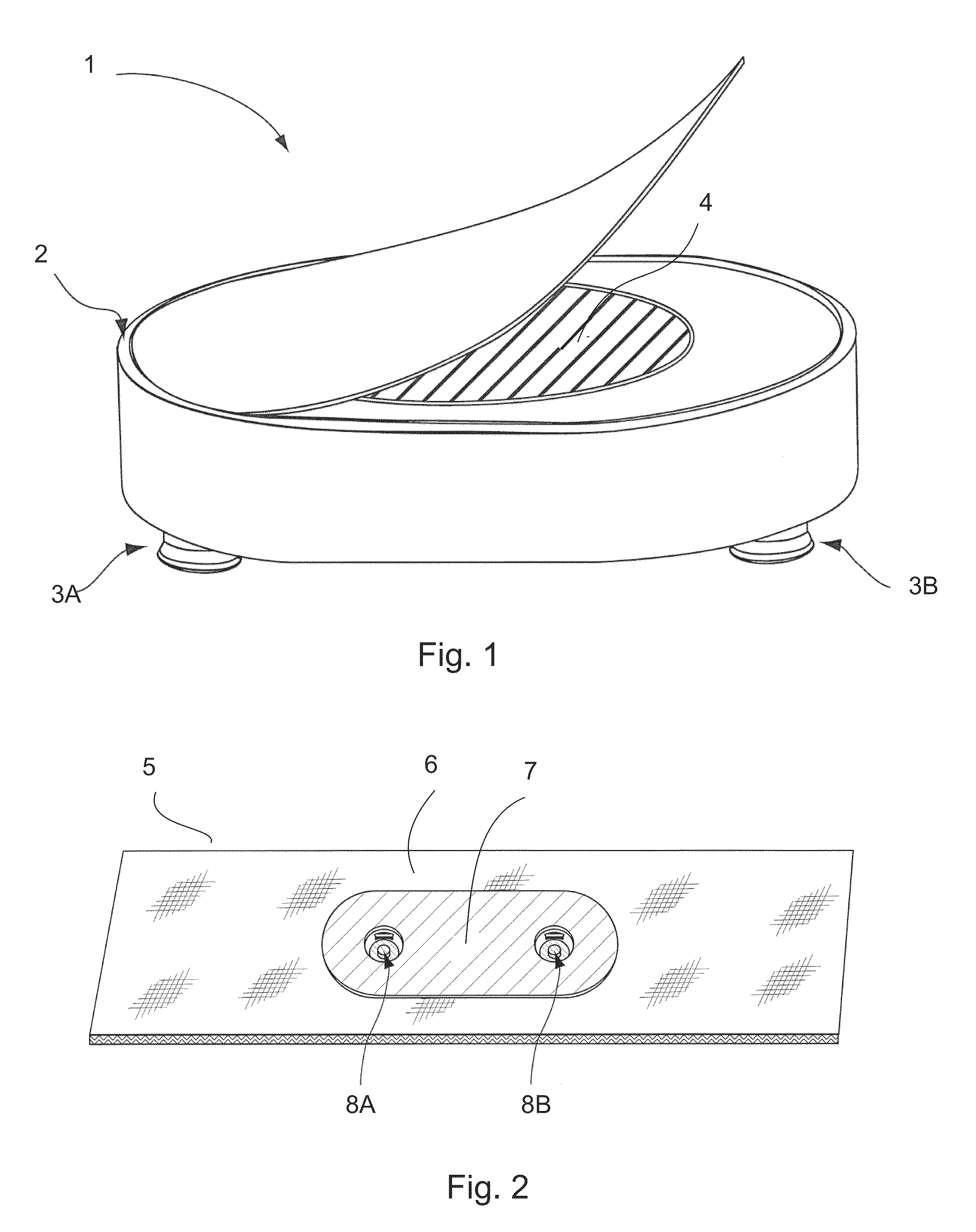
[0047]An example of a telemetric device 1 which is compatible with the garment 6 shown in FIG. 2. The telemetric device 1 has a body portion 2, an aperture 4 for housing for example a battery, a surface surrounding the aperture 4 surrounded by an outer lip 2a and a cover 3, which can be for example a flexible sticker type cover with or without a graphic or textual display. Additionally, the telemetric device has two studs 5 having an exposed male end for being detachably coupled to the snaps 8A and 8 of garment 6.

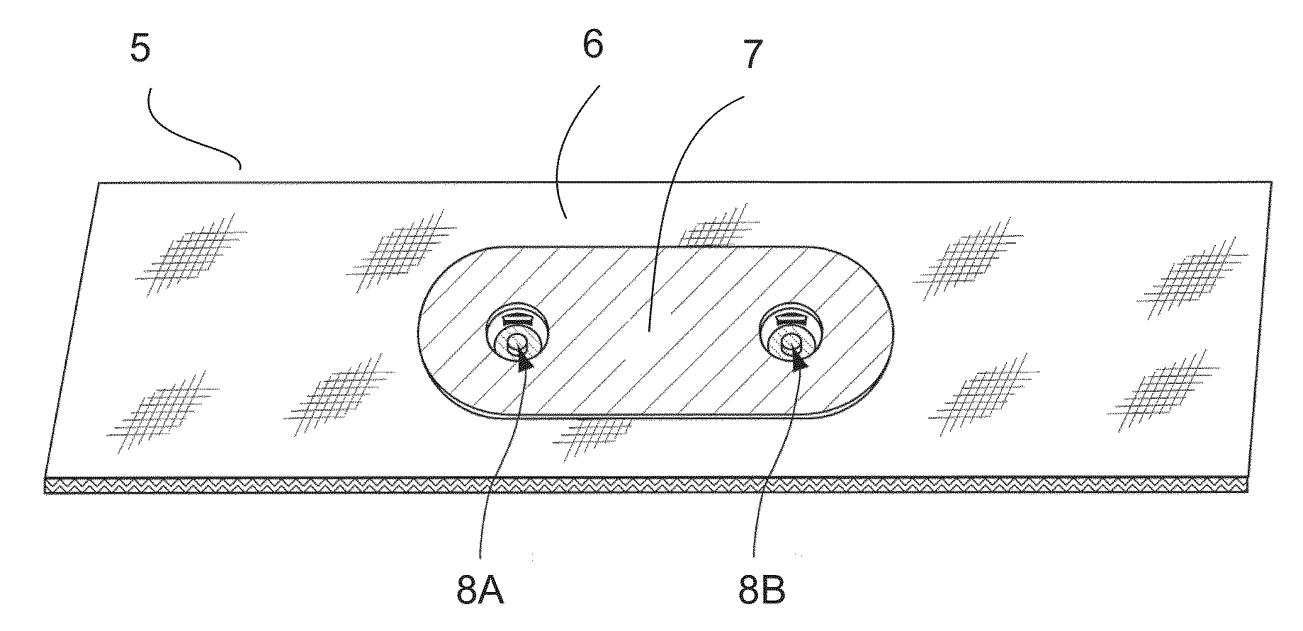
[0048]FIG. 2 shows an example of a garment or belt 6 which has a top material layer 7 and two electrodes (not shown) which can be coupled to the back of garment 6 or to another subsequent material layer. Each electrode is connected to a snap, 8A and 8B. In a typical arrangement, the electrode attached to each snap would extend in a direction away from the other snap. As such, there will be an area between the two snaps which may or may not include an electrode or similar ma...


PUM

PropertyMeasurementUnit
thicknessaaaaaaaaaa
snap thicknessaaaaaaaaaa
thicknessaaaaaaaaaa

Abstract

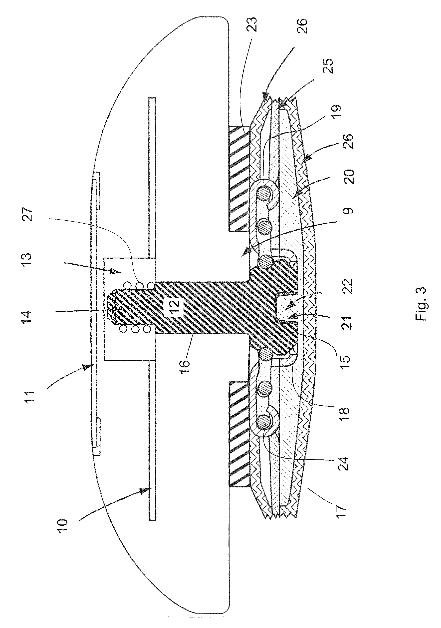
The invention concerns an electronic device, method for assembling components of an electronic device and a flexible cap for facilitating assembly of an electronic component of an electronic device. The electronic device has a housing and at least one male connection portion for providing a detachable connection of the electronic device to a female snap, and where the male connection portion comprises an elongate stud. An end portion of said stud is adapted to receive a flexible cap of a conductive sheet material having a top surface to fit on the top of the stud and at least two side elements, The side elements are formed as legs joined to the top surface by a first bend of the sheet material and are aligned generally along the wall of the end portion of the stud. An electrical connection and a mechanical lock between the end portion and the printed circuit board is created by flexible deformation of the side members when sliding the cap and the end portion through an aperture in the printed circuit board.

Description

RELATED APPLICATIONS[0001]The present application claims priority to Finnish Patent Application Serial No. 20135650 filed on Jun. 14, 2013. The present application corresponds to co-pending U.K. Patent Application No. 1310635.6.FIELD OF INVENTION[0002]The present invention relates to connectors in devices relating to health, sports and other personal equipment. More specifically, the present invention relates to connectors conveying electrode and other low-voltage signals with high reliability requirements in a potentially harsh environment and while being subject to considerable mechanical stress. Such connectors are used for example in heart rate and electromyograph monitors for connecting a usually male connection portion detachably to a female snap in a belt or garment.BACKGROUND OF THE INVENTION[0003]Currently, there are heart rate monitor belts which people can wear underneath their clothing in order to monitor their heart rate. Such belts are typically designed such that a te...

Claims


Application Information

Patent Timeline
Patent Type & Authority Patents(United States)
IPC IPC(8): H01R13/11H01R12/79H01R12/70H01R12/58A61B5/02A61B5/0416H05K7/14H01R43/20H01R13/17H01R12/71A61B5/00A61B5/0492A61B5/274A61B5/296
CPCA61B5/0416A61B5/02H01R12/58H01R12/7029H01R12/79H05K7/14A61B5/0492A61B5/6804H01R12/712H01R13/17H01R43/205H01R13/11A61B2562/125Y10T29/49218A61B5/0002A61B5/02438A61B2562/227A61B5/274A61B5/296H01R4/26H01R12/585H01R12/7064H01R13/627H05K5/006H05K5/0069H01R11/01H01R13/41A61B5/00
Inventor SELBY, TAPIOLEHTINEN, OSSILINDMAN, ERIK
Owner SUUNTO OY
Learn More