
Method for using a shared frequency resource, method for manufacturing terminals, terminals and telecommunication system

a technology of shared frequency resource and manufacturing method, applied in the field of telecommunication, can solve the problems of complex and energy-consuming, difficult to maintain synchronization between distant terminals, and low efficiency, and achieve the effect of improving the synchronization efficiency and synchronization efficiency

Active Publication Date: 2015-06-02
SIGFOX
View PDF31 Cites 10 Cited by
  • Summary
  • Abstract
  • Description
  • Claims
  • Application Information

AI Technical Summary

Benefits of technology

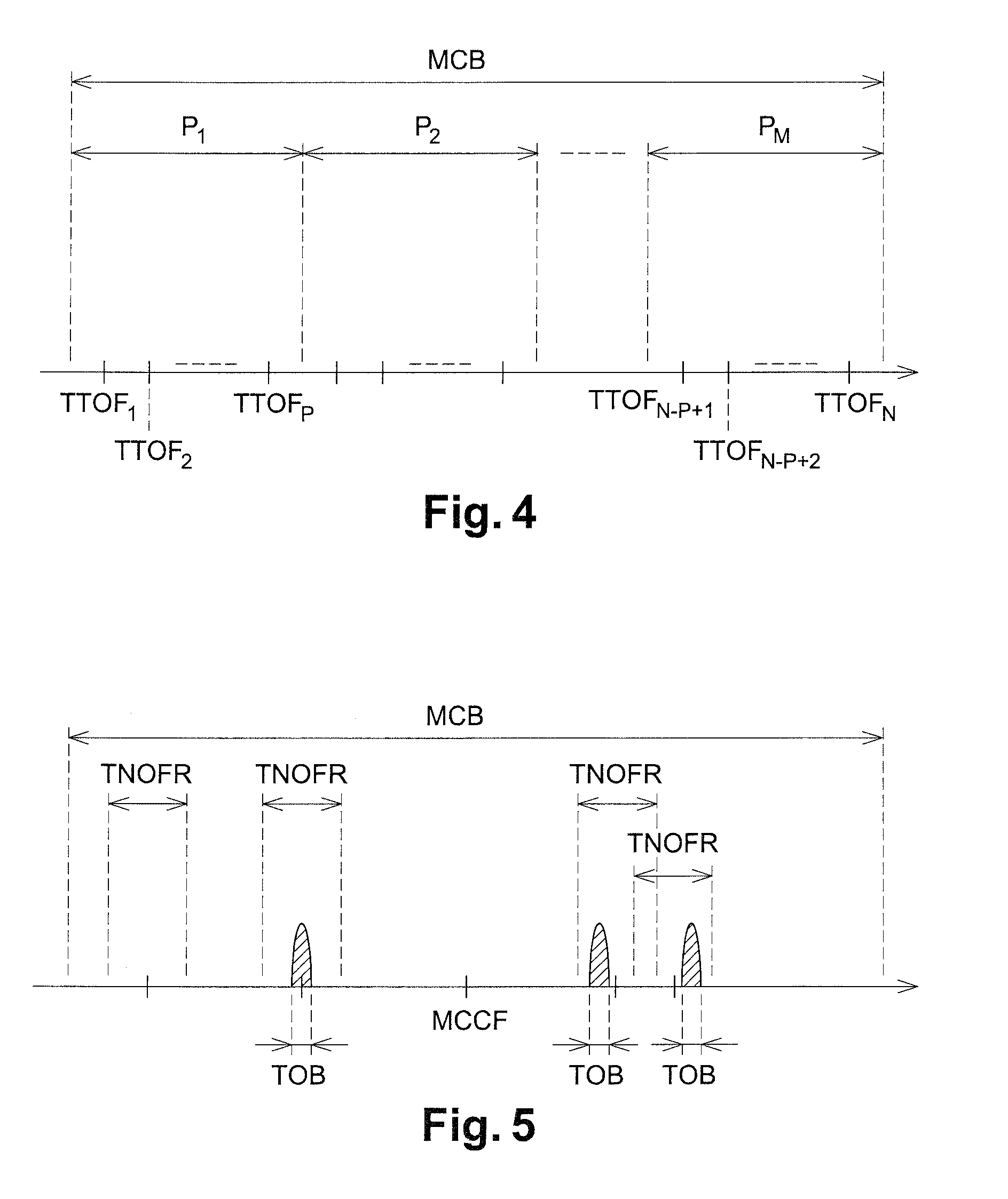
The present invention proposes a method for using a shared frequency resource between multiple terminals in telecommunication networks. The method is simple and inexpensive to implement, and can reduce collisions between radio signals emitted by different terminals. The invention also involves a terminal that transmits data using a shared frequency resource in a simple and autonomous manner. The invention can be used in low data rate information collection systems such as sensor networks. The technical effects of the invention include reducing synchronization requirements and simplifying the process of multiplexing radio signals.

Problems solved by technology

These assignment mechanisms require a strict time and / or frequency synchronization of a terminal with the station on the one hand and with the other terminals on the other hand, via an often complex and energy-consuming protocol, as this requires each terminal to be regularly switched on.
It is understood that these assignment mechanisms are incompatible with very low data rate telecommunication systems (a few bits per second), as these data rates are insufficient to maintain synchronization between the terminals and the station, and / or with very long-range telecommunication systems (several tens of kilometers in rural areas), as maintaining synchronization between distant terminals is very difficult (propagation delay, Doppler effect, etc.).

Method used


Image

  • Method for using a shared frequency resource, method for manufacturing terminals, terminals and telecommunication system
  • Method for using a shared frequency resource, method for manufacturing terminals, terminals and telecommunication system
  • Method for using a shared frequency resource, method for manufacturing terminals, terminals and telecommunication system

Examples


Embodiment Construction

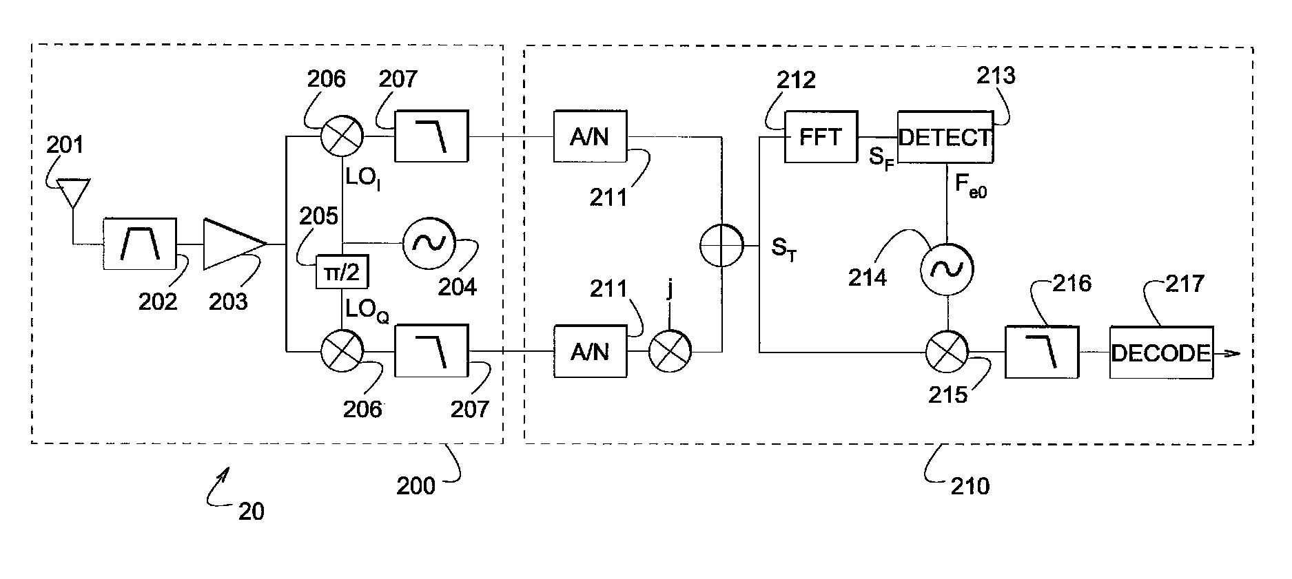
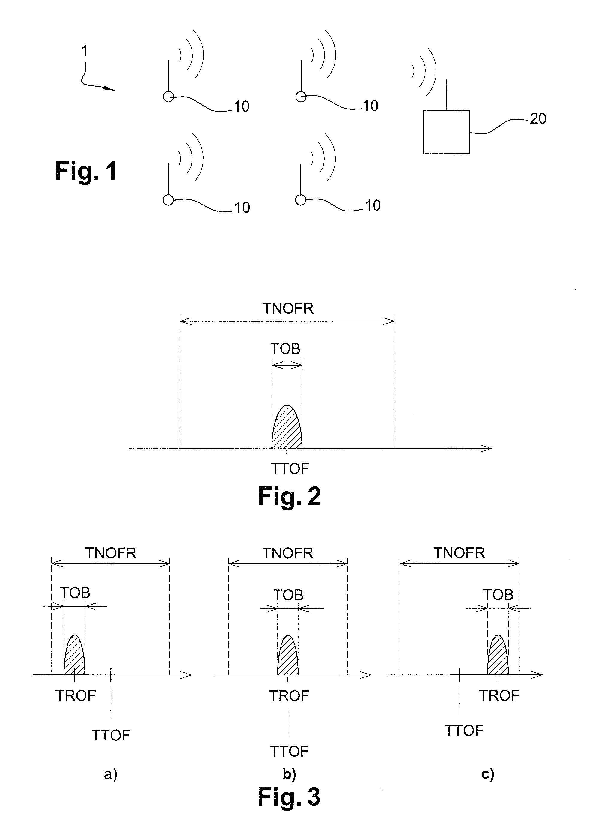
[0049]FIG. 1 represents, in a very schematic manner, a telecommunication system 1 comprising several terminals 10 and one station 20.

[0050]The invention is related to a method for using a frequency resource shared between several terminals 10 to emit data in the form of radio signals to the station 20.

[0051]In the context of the invention, “station” is understood in a general manner as a receiving device adapted to receive radio signals in all of the shared frequency resource. For example, station 20 is any one of terminals 10 or a specific device such as a wired or wireless telecommunication network access point, centralizing the data emitted by each of the terminals 10.

[0052]“Radio signal” is understood as an electromagnetic wave propagated via wireless means, the frequencies of which are comprised within the traditional radio wave spectrum (several hertz to several hundred gigahertz) or in adjacent frequency bands.

[0053]It should be noted that this invention mainly considers the ...


PUM

PropertyMeasurementUnit
frequencyaaaaaaaaaa
frequencyaaaaaaaaaa
frequencyaaaaaaaaaa

Abstract

A terminal (10) includes elements for transmitting data towards a station (20) in the form of radio signals, the radio signals being transmitted using a frequency resource (MC) shared between a plurality of terminals (10), characterized in that the terminal is configured to emit radio signals, the instantaneous frequency spectrum of which has a bandwidth (TOB) that is significantly lower than a frequency drift of a frequency synthesis unit of the terminal. Also disclosed are a method for using a frequency resource, a method for manufacturing terminals (10) and a telecommunication system (1).

Description

BACKGROUND OF THE INVENTION[0001]1. Field of the Invention[0002]The present invention relates to the field of telecommunication and in particular to that of wireless telecommunication. The present invention is more particularly related to the multiplexing of radio signals emitted by different terminals sharing the same frequency resource.[0003]2. Description of the Related Art[0004]The main known techniques for multiplexing radio signals in current telecommunication networks, to enable different terminals to access a shared frequency resource to communicate with a station, consist mainly in multiplexing said radio signals:[0005]by emitting them in different frequency subbands (“Frequency Division Multiple Access” or FDMA);[0006]by emitting them at different time intervals (“Time Division Multiple Access” or TDMA);[0007]by spreading their frequency spectrum by means of codes that are generally substantially orthogonal to each other (“Code Division Multiple Access” or CDMA).[0008]Each...

Claims


Application Information

Patent Timeline
Patent Type & Authority Patents(United States)
IPC IPC(8): H04W74/08G06F17/14H04B1/10H04B3/32H04B3/44H04B7/00H04J1/12
CPCH04W74/085H04J1/12Y10T29/49002H04B7/00H04B3/32H04B3/44H04B1/10G06F17/14
Inventor FOURTET, CHRISTOPHEBAILLEUL, THIERRY
Owner SIGFOX
Learn More