Systems and method for detecting contact with a display panel by asymetric detection waveform

a detection waveform and display panel technology, applied in the field of touch panels, can solve the problems of complex circuit configuration, large selection time, and high cost, and achieve the effects of reducing disturbance noise, reducing time consumption, and simplifying the detection circui

Active Publication Date: 2015-06-02
JAPAN DISPLAY INC
View PDF15 Cites 4 Cited by
  • Summary
  • Abstract
  • Description
  • Claims
  • Application Information

AI Technical Summary

Benefits of technology

[0009]As another method of removing the disturbance noise, a generally-known noise filter is considered to be used. For example, a low-pass filter having a cutoff frequency lower than the relevant Nyquist frequency is inserted before A / D conversion, thereby folding noise may be removed. Thus, the disturbance noise may be removed, and a detection circuit may be simplified after A / D conversion. However, a touch signal in synchronization with a drive signal outputted from a touch panel is a positive-negative symmetrical polarity-alternating signal and therefore may not pass through the low-pass filter. Specifically, the low-pass filter removes not only the disturbance noise but also the touch signal.
[0010]It is desirable to provide a method of driving a touch panel, in which presence of touch may be securely detected while influence of the disturbance noise and touch detection time are reduced despite using a relatively simple circuit configuration, and provide a touch panel and a display apparatus with a touch detection function using the drive method each.
[0019]According to the method of driving a touch panel, the capacitance-type touch panel, and the display device with a touch detection function of the embodiment of the invention, when an external proximity object exists, a touch component included in a detection signal from a touch detection electrode has positive-negative asymmetry, therefore even if signal processing of a detection signal is performed via an analog filter for noise removal, the touch component is not removed from the detection signal. Therefore, the touch signal may be securely detected while removing disturbance noise. Moreover, since processing of sequentially changing frequency of a drive signal to select a detection condition is unnecessary unlike in the past, reduction in size of a detection circuit and decrease in detection time may be achieved.

Problems solved by technology

However, in the drive method of the capacitance-type touch panel and the detection method thereof disclosed in the above-mentioned United States Patent Application Publication, since a frequency of a drive signal needs to be sequentially changed to select a condition at which a touch signal is hardly affected by disturbance noise, much time may be taken for selecting the condition.
Furthermore, preparation of drive signals having a plurality of frequencies is necessary, and switching timing of the signals needs to be determined, so that a circuit configuration may be complicated and large.
However, a touch signal in synchronization with a drive signal outputted from a touch panel is a positive-negative symmetrical polarity-alternating signal and therefore may not pass through the low-pass filter.

Method used


Image

  • Systems and method for detecting contact with a display panel by asymetric detection waveform
  • Systems and method for detecting contact with a display panel by asymetric detection waveform
  • Systems and method for detecting contact with a display panel by asymetric detection waveform

Examples


first embodiment

2. First Embodiment

Configuration Example

General Configuration Example

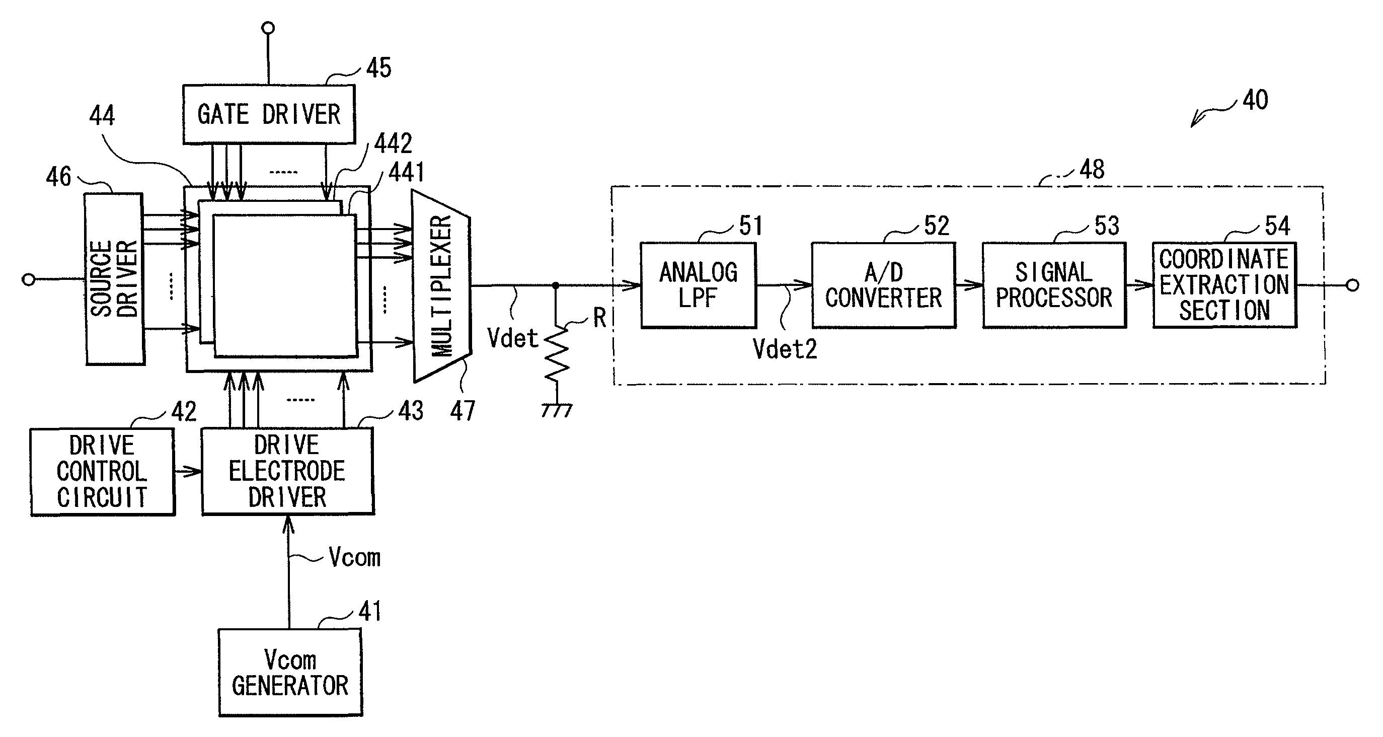
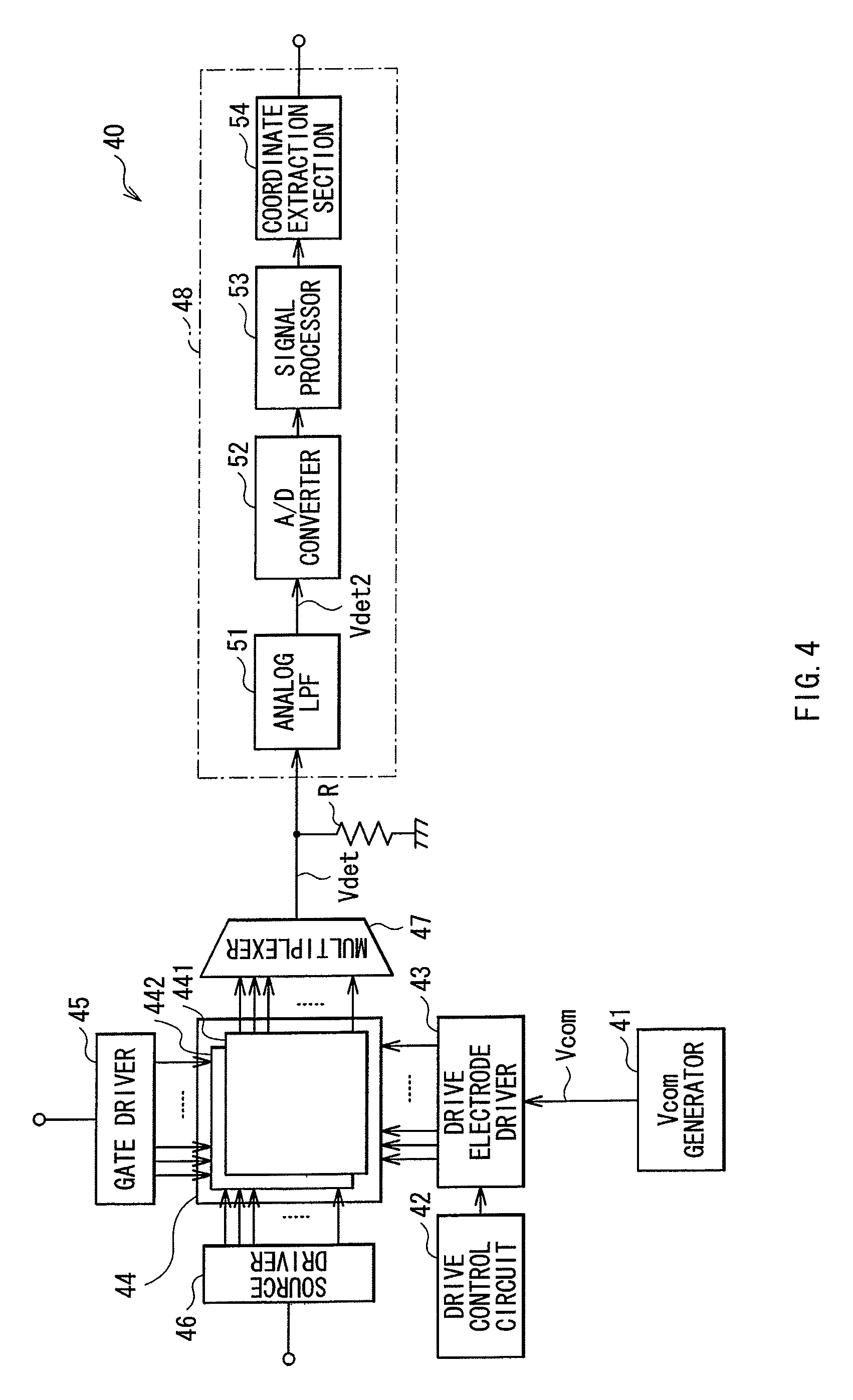
[0055]FIG. 4 shows a configuration example of a display apparatus with a touch detection function according to a first embodiment of the invention. Since a method of driving a touch panel according to an embodiment of the invention is embodied by the embodiment, the method is described together. The display apparatus is a so-called in-cell type apparatus where liquid crystal display elements are used as display elements, and besides, a liquid crystal display device configured of the liquid crystal display elements is integrated with a capacitance-type touch sensor.

[0056]The display apparatus with a touch detection function 40 includes a Vcom generator 41, a drive control circuit 42, a drive electrode driver 43, a display device with a touch detection function 44, a gate driver 45, a source driver 46, a multiplexer 47, a detection circuit 48, and a resistance R.

[0057]The Vcom generator 41 is a circuit generating a d...

second embodiment

3. Second Embodiment

[0120]Next, a display apparatus with a touch detection function according to a second embodiment of the invention is described. Substantially the same components as those of the display apparatus with a touch detection function according to the first embodiment are marked with the same reference numerals or signs, and appropriately omitted to be described.

[0121]Configuration Example

General Configuration Example

[0122]FIG. 15 shows a configuration example of a display apparatus with a touch detection function 140 according to the embodiment.

[0123]The display apparatus with a touch detection function 140 includes a Vcom generator 41, a drive control circuit 142, a drive electrode driver 43, a display device with a touch detection function 44, a gate driver 45, a source driver 46, a multiplexer 47, a detection circuit 148, and a resistance R.

[0124]The drive control circuit 142 selects and controls an electrode from a plurality of drive electrodes of the display devic...

application examples

4. Application Examples

[0152]Next, application examples of the method of driving a touch panel, the capacitance-type touch panel, and the display apparatus with a touch detection function, those being described in the embodiments and the modifications, are described with reference to FIG. 19 to FIG. 23G The method of driving a touch panel, the capacitance-type touch panel, and the display apparatus with a touch detection function according to the embodiments and the like may be applied to electronic devices in any field, including a television apparatus, a digital camera, a notebook personal computer, a mobile terminal such as mobile phone, and a video camera. In other words, the display apparatus according to each of the embodiments and the like may be applied to electronic devices in any field, which displays an externally inputted video signal or internally generated video signal as an image or a picture.


PUM

PropertyMeasurementUnit
frequencyaaaaaaaaaa
capacitanceaaaaaaaaaa
surface areaaaaaaaaaaa

Abstract

A capacitance-type touch panel, allowing disturbance noise and touch detection time to be reduced and having a simple configuration, is provided. The capacitance-type touch panel including: a plurality of drive electrodes each having a strip shape; a drive control circuit performing control such that a drive signal for touch detection is selectively applied to the drive electrodes; a plurality of touch detection electrodes arranged to intersect with the drive electrodes in such a manner that capacitance is formed in each intersecting part, and each outputting a detection signal in synchronization with the drive signal; and a detection circuit detecting an external proximity object based on the detection signal. The drive control circuit controls application of the drive signal in such a manner that the detection signal is a polarity-alternating signal including a positive-negative asymmetrical signal component which is due to presence of the external proximity object.

Description

[0001]The present application claims priority to Japanese Patent Application No. JP2009-154207 filed in the Japanese Patent Office on Jun. 29, 2009, the entire content of which is hereby incorporated by reference.BACKGROUND OF THE INVENTION[0002]1. Field of the Invention[0003]The present invention relates to a touch panel that may be inputted with information by contact or approach of a user with a finger or the like, and particularly relates to a method of driving a touch panel detecting touch based on change in capacitance, and a touch panel and a display apparatus with a touch detection function using the method each.[0004]2. Description of Related Art[0005]A display device is recently noticed, in which a contact detector, so-called touch panel, is mounted on a display device such as liquid crystal display device, and various button images are displayed on the display device so as to allow information input as a substitute for typical mechanical buttons. While several types of to...

Claims


Application Information

Patent Timeline
Patent Type & Authority Patents(United States)
IPC IPC(8): G06F3/044G02F1/1333
CPCG06F3/044G02F1/13338G06F3/0446
Inventor NOGUCHI, KOUJIHARADA, TSUTOMUKIDA, YOSHITOSHINAKANISHI, TAKAYUKIISHIZAKI, KOJITAKEUCHI, TAKEYA
Owner JAPAN DISPLAY INC
Why Eureka
Try Eureka