
Systems and methods for reducing off-axis optical aberrations in wavelength dispersed devices

a wavelength dispersed optical and wavelength-dispersed technology, applied in the field of optical systems, can solve the problems of loss of signal information, increasing importance of off-axis and outside the paraxial region propagation of beams, and increasing the effects of optical aberration

Active Publication Date: 2015-06-02
II VI DELAWARE INC
View PDF5 Cites 1 Cited by
  • Summary
  • Abstract
  • Description
  • Claims
  • Application Information

AI Technical Summary

Benefits of technology

This patent describes systems and methods for reducing optical aberrations in devices that disperse light in different directions. The invention uses a polarization diversity element to separate and recombinate polarization states, with a passive beam correcting element to reduce position-dependent focusing. The optical system also includes an arcuate collimating region to reduce field curvature aberrations. The invention selectively corrects the trajectories of separated polarization states to reduce polarization dependent loss. Overall, this patent provides improved systems for optical dispersion devices with reduced off-axis optical aberrations.

Problems solved by technology

Optical systems suffer loss due to various forms of optical aberration, which lead to loss in signal information.
However, as more complex devices are built to perform advanced functions, the need to propagate beams off-axis and outside the paraxial region is becoming increasingly important.
Therefore, with higher port count devices, fibers extend further from the optical axis and switching optical beams to those fibers means that the effects of optical aberrations become greater.
Another issue contributing to aberrations is the size and profile of an optical beam.
These effects are undesirable from a performance point of view.
However, to the inventors' knowledge, no suitable techniques have been developed to actively address the above-mentioned aberrations at a system level, particularly in higher port count optical devices and devices incorporating asymmetric beams profiles.
In particular, the device of U.S. Pat. No. 6,813,080 is not suitable for reducing loss in an optical system other than the PDL specifically introduced by an alternative grating / grism.
Unlike other types of optical loss, PDL cannot be easily compensated for by simple amplification.

Method used


Image

  • Systems and methods for reducing off-axis optical aberrations in wavelength dispersed devices
  • Systems and methods for reducing off-axis optical aberrations in wavelength dispersed devices
  • Systems and methods for reducing off-axis optical aberrations in wavelength dispersed devices

Examples


Embodiment Construction

Outline of the Relevant Optical Systems

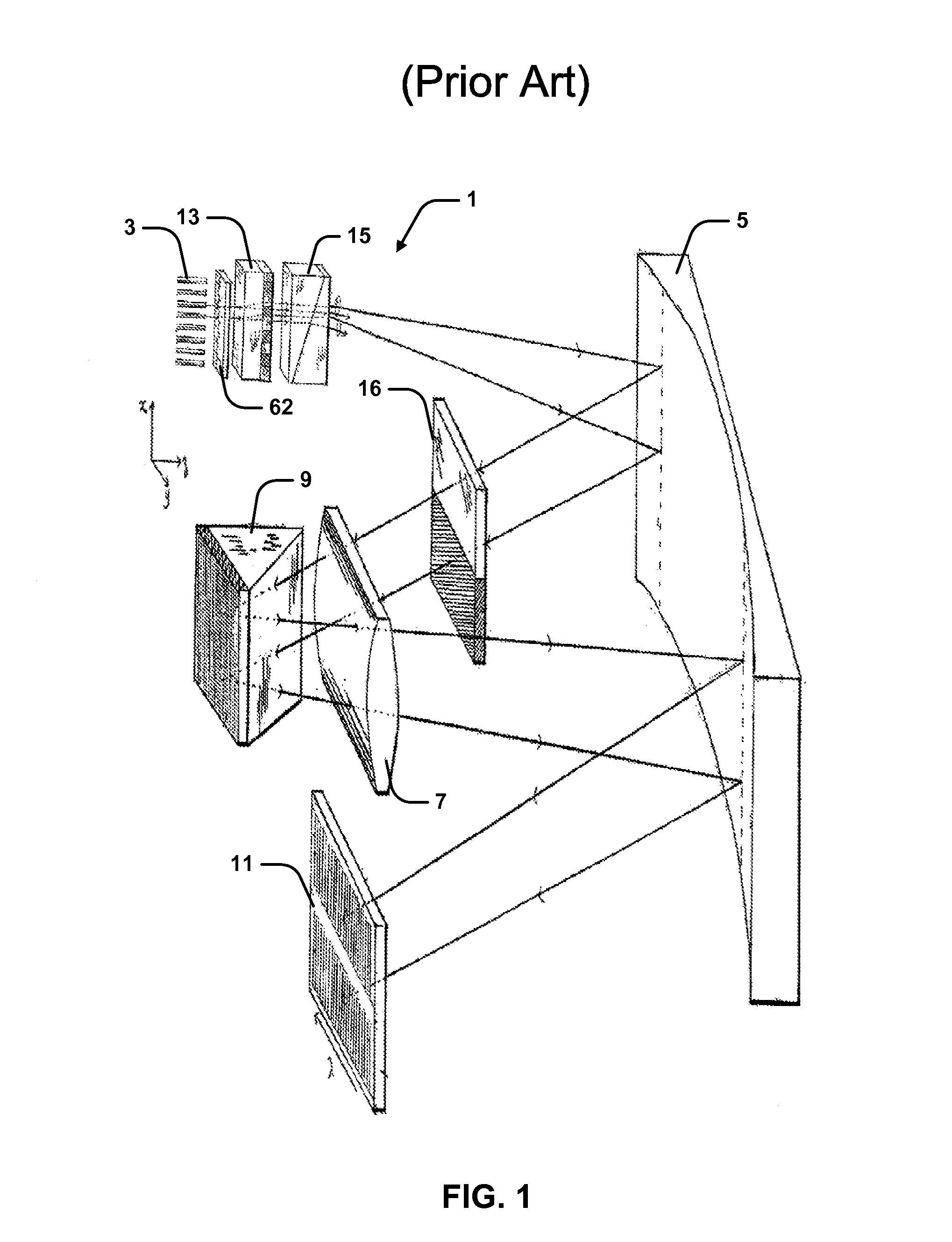
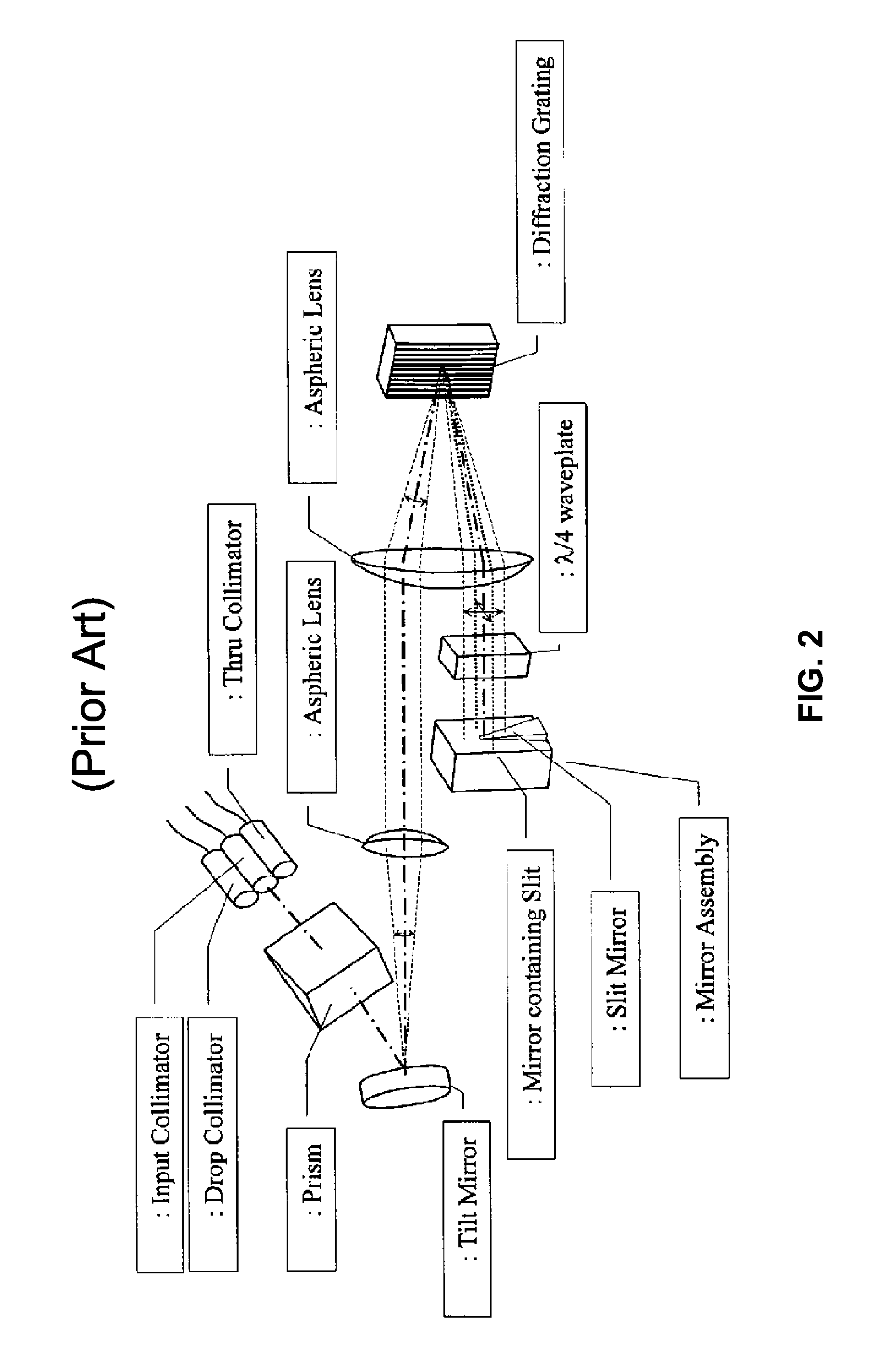
[0070]Referring initially to FIGS. 1 to 3, there are illustrated examples of known wavelength selective switches (WSS). FIG. 1 illustrates an LCOS-based WSS utilizing a reflective liquid crystal phase matrix to switch wavelength channels (from U.S. Pat. No. 7,397,980 entitled “Dual-Source Optical Wavelength Processor” to Frisken and assigned to Finisar Corporation). FIG. 2 illustrates a MEMS-based WSS device utilizing a two-dimensional array of reflective micro electromechanical (MEMS) mirrors for steering and switching wavelength channels (from U.S. Pat. No. 7,408,639 entitled “Tunable Optical Routing System” to Strasser et al. and assigned to Nistica, Inc.). FIG. 3 illustrates another MEMS-based switch (from Reissued U.S. Pat. No. RE39,411 entitled “Reconfigurable All-Optical Multiplexers With Simultaneous Add-Drop capability” to Belser et al. and assigned to Capella Photonics, Inc.).

[0071]Considered collectively, the devices of FIGS. 1 to 3 ...


PUM


Abstract

Through its higher refractive index, a silicon grism can be used to reduce the Described herein are systems and methods for reducing optical aberrations in an optical system to decrease polarization dependent loss. Embodiments are provided particularly to define beam trajectories through an optical switching system which reduce off-axis aberrations. In one embodiment, a silicon grism is provided for reducing the curvature of the focal plane at an LCOS device in a wavelength selective switch (WSS) such that the separated polarization states converge at the LCOS at substantially the same point along the optical axis for all wavelengths. In this embodiment, an axial offset at the LCOS device will not produce large PDL at the coupling fibers. In another embodiment, a coupling lens having an arcuate focusing region is provided to address an offset in the optical beams, such that the separated polarization states couple symmetrically to respective output fibers.

Description

CROSS REFERENCE TO RELATED APPLICATIONS[0001]The present application is a non-provisional of U.S. Provisional Patent Application Ser. No. 61 / 579,564, filed Dec. 22, 2011. The entire contents of U.S. Provisional Application Ser. No. 61 / 579,564, is herein incorporated by reference.FIELD OF THE INVENTION[0002]The present invention relates to optical systems and in particular to systems and methods for reducing off-axis optical aberrations in wavelength dispersed optical devices / systems. While some embodiments will be described herein with particular reference to that application, it will be appreciated that the invention is not limited to such a field of use, and is applicable in broader contexts.BACKGROUND[0003]Any discussion of the background art throughout the specification should in no way be considered as an admission that such art is widely known or forms part of common general knowledge in the field.[0004]Optical systems suffer loss due to various forms of optical aberration, wh...

Claims


Application Information

Patent Timeline
Patent Type & Authority Patents(United States)
IPC IPC(8): G02B6/00G02B6/27G02B6/293G02B6/35
CPCG02B6/354G02B6/3594G02B6/29397G02B6/356G02B6/2793G02B6/2931G02B6/29373
Inventor STEWART, LUKEBAXTER, GLENN WAYNE
Owner II VI DELAWARE INC
Learn More