
Cylinder injection engine

a technology of sparkignition and injection engine, which is applied in the direction of combustion engines, electric control, machines/engines, etc., can solve the problems of degrading fuel consumption efficiency during homogenous combustion and difficult to increase the maximum engine output, and achieve the effect of not reducing the persistence of tumble flow

Inactive Publication Date: 2015-06-02
SUBARU CORP
View PDF10 Cites 2 Cited by
  • Summary
  • Abstract
  • Description
  • Claims
  • Application Information

AI Technical Summary

Benefits of technology

[0009]In view of the above-described situation, an object of the present invention is to provide a cylinder injection engine capable of appropriately stratifying the fuel-air mixture during the stratified charge combustion without reducing the persistence of the tumble flow of the intake air during the homogeneous combustion.
[0011]The cylinder injection engine according to the present invention is capable of appropriately stratifying the fuel-air mixture during the stratified charge combustion without reducing the persistence of the tumble flow of the intake air during the homogeneous combustion.

Problems solved by technology

Therefore, as a result, there is a risk that the fuel consumption efficiency during the homogeneous combustion will be degraded.
However, these devices may serve as a flow-passage resistance, which makes it difficult to increase the maximum engine output.

Method used


Image

  • Cylinder injection engine
  • Cylinder injection engine
  • Cylinder injection engine

Examples


Embodiment Construction

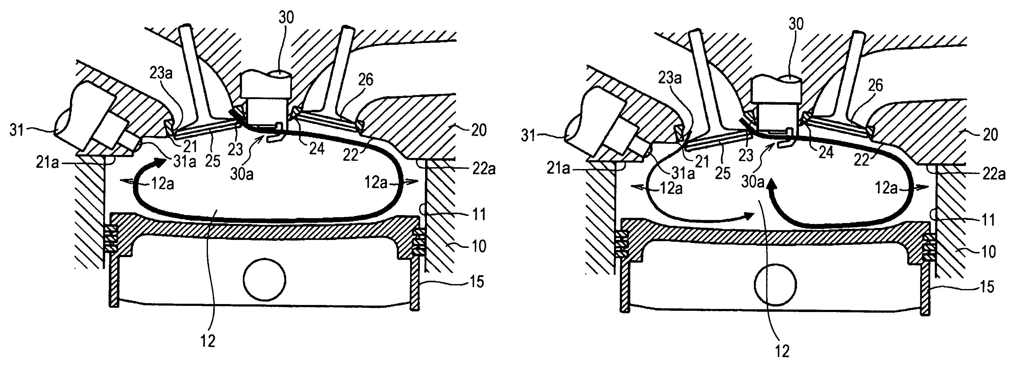
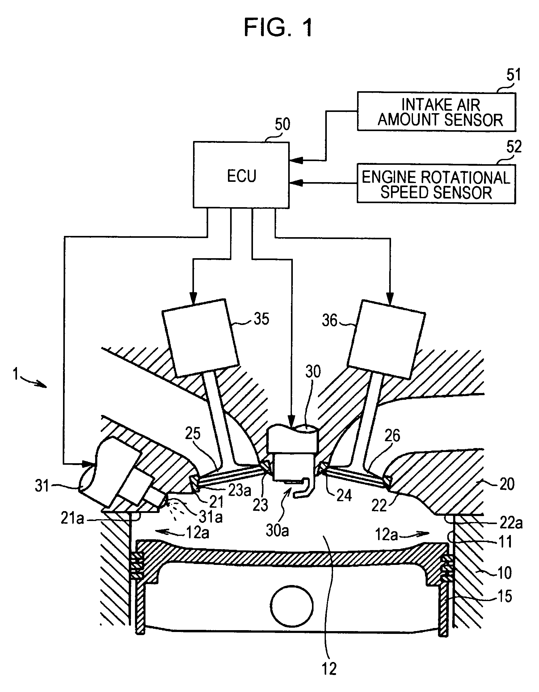
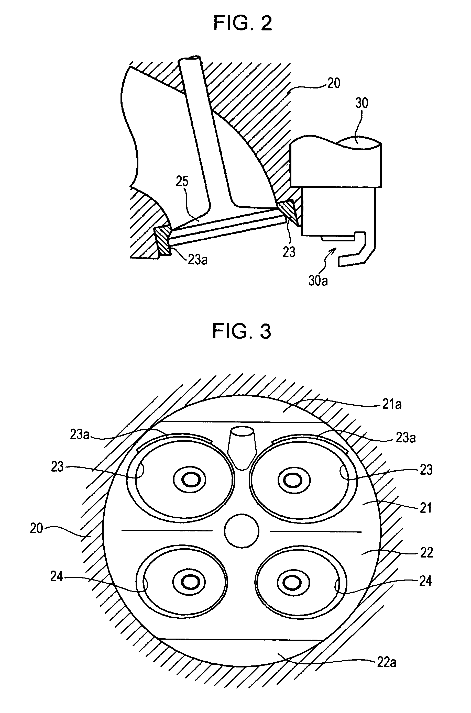
[0024]An embodiment of the present invention will now be described with reference to the accompanying drawings. The drawings illustrate the embodiment of the present invention. FIG. 1 is a schematic diagram illustrating the main part of an engine. FIG. 2 is a sectional view of an area around an intake port of a cylinder head. FIG. 3 is a bottom view of the cylinder head. FIG. 4 is a flowchart of a routine for setting control parameters of the engine. FIG. 5 is a diagram illustrating control states corresponding to respective operating ranges. FIG. 6 is a graph illustrating the relationship between the engine rotational speed, the engine load, and the operating ranges. FIG. 7A is a diagram illustrating the relationship between an intake valve and a mask when a maximum lift of the intake valve is set to a low lift. FIG. 7B is a diagram illustrating the manner in which a tumble flow is generated when the maximum lift of the intake valve is set to the low lift. FIG. 8A is a diagram illu...


PUM


Abstract

A mask portion is provided at a partial area of an intake port at a side opposite to an exhaust port. The mask portion prevents a part of the intake port from being opened when the intake valve is in a low lift state. A top surface of a piston includes a smooth surface. An ECU sets the maximum lift of the intake valve for a variable valve mechanism to an intermediate lift and sets a fuel injection timing for an injector to a compression stroke when an operating range of the engine is a fast idle range. The intermediate lift is an amount of lift at which the intake valve is moved beyond the mask portion and a flow rate of intake air in the partial area is limited relative to a flow rate of the intake air in other areas owing to the mask portion.

Description

CROSS-REFERENCE TO RELATED APPLICATIONS[0001]The present application claims priority from Japanese Patent Application No. 2009-291112 filed on Dec. 22, 2009, the entire contents of which are hereby incorporated by reference.BACKGROUND OF THE INVENTION[0002]1. Field of the Invention[0003]The present invention relates to a spark-ignition cylinder injection engine which directly injects fuel into a cylinder using a high-pressure injector.[0004]2. Description of the Related Art[0005]In general, a cylinder injection engine is capable of accurately controlling parameters such as a fuel injection timing and an amount of fuel injection. Therefore, selective switching between homogeneous combustion (premixed homogeneous combustion) and stratified charge combustion can be easily performed in accordance with an operating state of the engine. The stratified charge combustion may be performed, for example, in a fast idle period immediately after the start of the engine. Accordingly, ignition tim...

Claims


Application Information

Patent Timeline
Patent Type & Authority Patents(United States)
IPC IPC(8): F02D43/00F02B23/10F02D13/02
CPCF02B23/105F02D13/0215F02D13/0246F02D13/0261F02B2023/102F02B2023/106Y02T10/125Y02T10/18Y02T10/12
Inventor KANEKO, MAKOTO
Owner SUBARU CORP
Learn More