
Method of manufacturing corrugated preform using braiding process

a manufacturing method and technology of corrugated preforms, applied in the direction of braids, springs, textiles and paper, etc., can solve the problems of difficult to maintain the constant application of the above spring to the suspension of the vehicle, the forming process may be more complex, and the above spring may not be applied to a mass production

Active Publication Date: 2015-05-26
HYUNDAI MOTOR CO LTD +1
View PDF18 Cites 13 Cited by
  • Summary
  • Abstract
  • Description
  • Claims
  • Application Information

AI Technical Summary

Benefits of technology

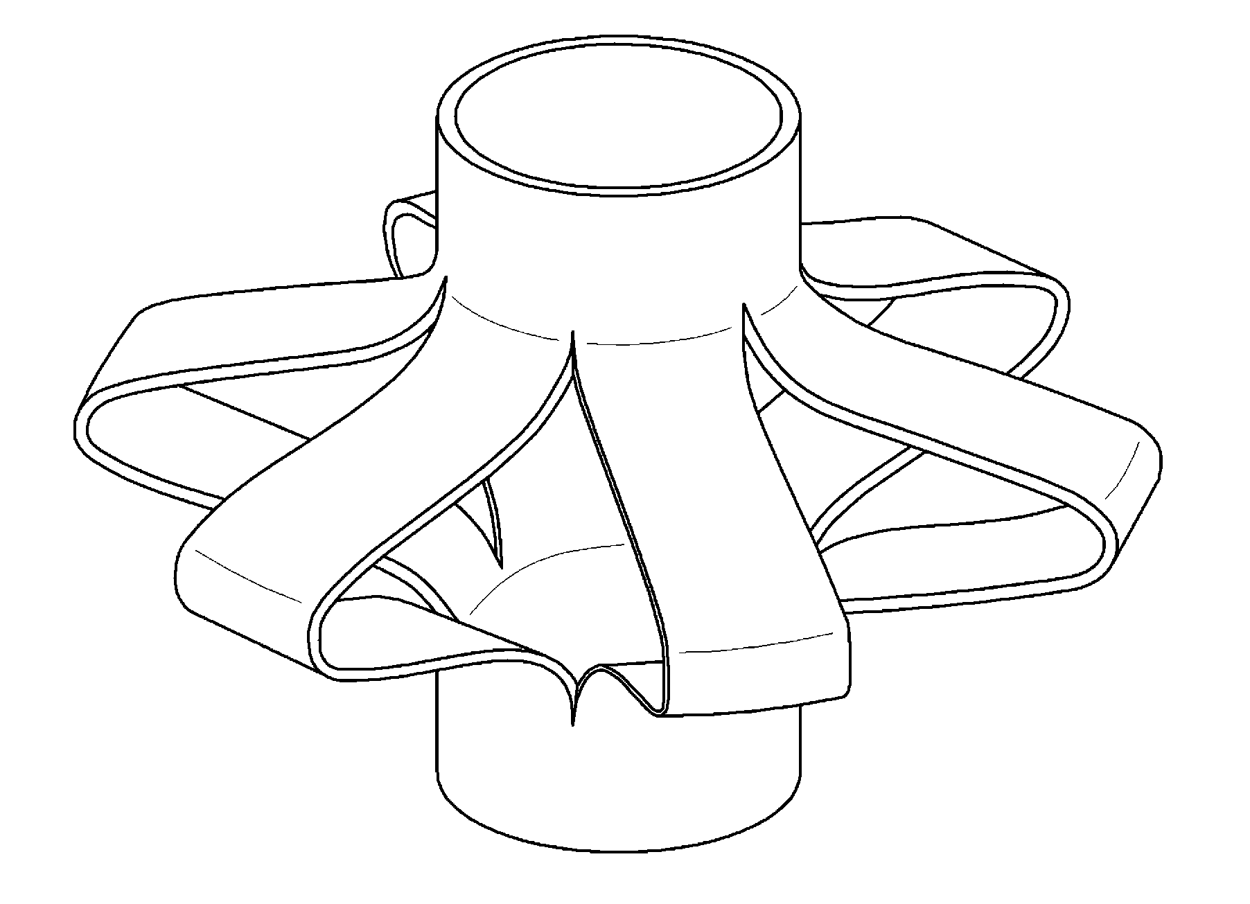
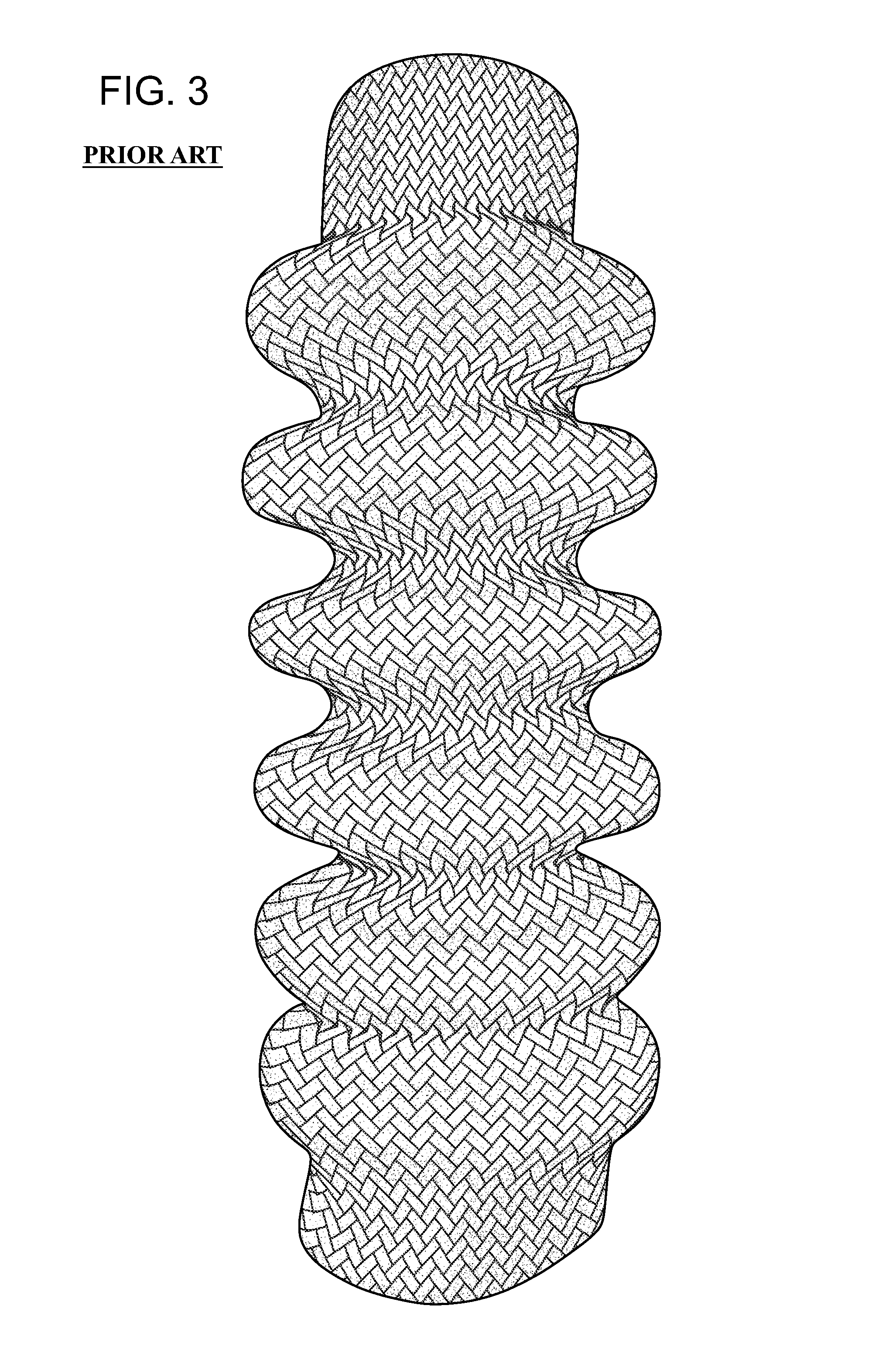
[0013]The present invention provides a method of maintaining a substantially similar fiber volume fraction and orientation angle of a concave portion and a convex portion, when the preform having a wrinkle shape is manufactured based on a braiding process, and more particularly, a method of manufacturing a corrugated preform using a braiding process. In addition, the present invention provides a method which may manufacture the concave portion and the convex portion to have substantially the same fiber volume fraction and orientation angle by braiding the concave portion by the same method as a method for a braid having a cylinder shape, and braiding the convex portion in a separation structure by installing, in braiding equipment, a locking apparatus or an apparatus which reversely rotates.
[0015]In addition, the braiding a composite material corresponding to an outer diameter of a cylindrical cylinder shape and the braiding the composite material by connecting a plurality of separate composite materials to one side of the braided composite material may be applied to a process of manufacturing the concave portion of the corrugated preform. In addition, the braiding a composite material corresponding to an outer diameter of a cylindrical cylinder shape and the braiding the composite material to one side of the separate composite material corresponding to an outer diameter of the cylindrical cylinder shape may braid the composite material while rotating in a predetermined direction.

Problems solved by technology

However, when the material of the coil spring is substituted with the plastic composite material while maintaining the coil shape of the coil spring, it may be difficult to maintain a spring constant applied to the suspension of the vehicle due to a difference in absolute rigidity between the metallic material and the plastic composite material.
In addition, in the coil spring, the spring constant may be partially improved by increasing a diameter and a width of the wire and applying a material having greater rigidity while maintaining the coil shape, however, since there may be difficulty in applying the above spring material having high rigidity due to an increase in weight and cost, the above spring may not be applied to a mass production.
However, since the closed cross sectional shape is manufactured by using a composite material having substantially high rigidity to implement the spring constant that can be applied to the suspension of the vehicle, the forming process may be more complex, and mass production may be difficult due to low productivity.
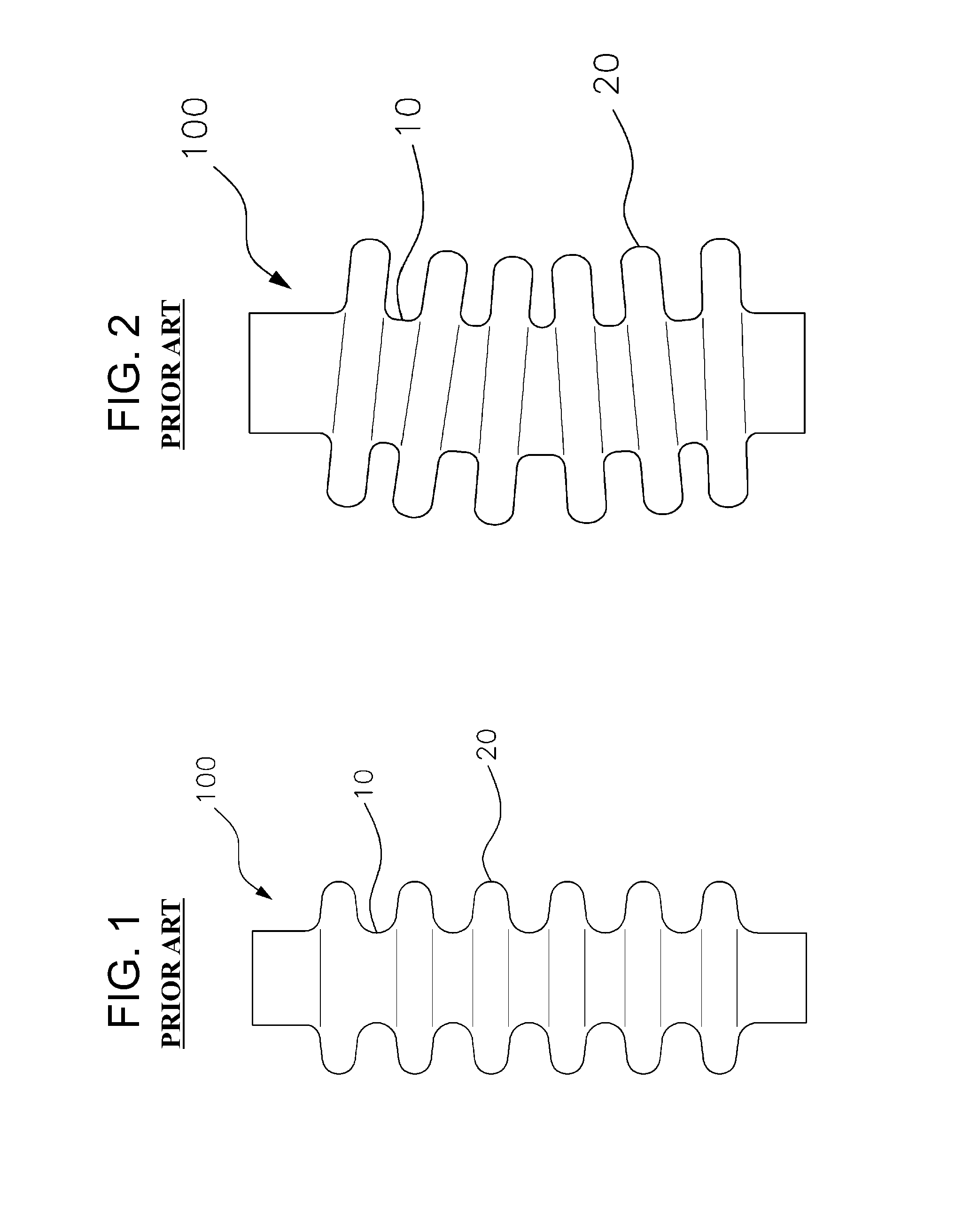
Moreover, since the material that may be applied to the hollow corrugated spring 100 is limited to pure thermoplastic resin or a plastic composite material which contains a reinforcing material of an amount equal to or less than a predetermined amount, and it may be possible to manufacture the entire corrugated spring using a single material, sufficient insulation performance with respect to vibration and noise may not be secured.
However, when a process such as a hand lay-up process is applied, costs may increase due to an excessive process time, it may be difficult to implement uniform deformation and physical properties due to a difference of the physical properties caused by a change of a cross sectional area, and therefore a buckling phenomenon, as illustrated in FIG. 2, may occur when the spring is deformed by a load.

Method used


Image

  • Method of manufacturing corrugated preform using braiding process
  • Method of manufacturing corrugated preform using braiding process
  • Method of manufacturing corrugated preform using braiding process

Examples


Embodiment Construction

[0031]It is understood that the term “vehicle” or “vehicular” or other similar term as used herein is inclusive of motor vehicles in general such as passenger automobiles including sports utility vehicles (SUV), buses, trucks, various commercial vehicles, watercraft including a variety of boats and ships, aircraft, and the like, and includes hybrid vehicles, electric vehicles, combustion, plug-in hybrid electric vehicles, hydrogen-powered vehicles and other alternative fuel vehicles (e.g. fuels derived from resources other than petroleum).

[0032]The terminology used herein is for the purpose of describing particular embodiments only and is not intended to be limiting of the invention. As used herein, the singular forms “a”, “an” and “the” are intended to include the plural forms as well, unless the context clearly indicates otherwise. It will be further understood that the terms “comprises” and / or “comprising,” when used in this specification, specify the presence of stated features,...


PUM

PropertyMeasurementUnit
outer diameteraaaaaaaaaa
volume fractionaaaaaaaaaa
orientation angleaaaaaaaaaa

Abstract

A method of manufacturing a corrugated preform that allows a fiber volume fraction and an orientation angle to be substantially the same at a concave portion and at a convex portion when the corrugated preform is manufactured based on a braiding process. The method includes braiding a composite material corresponding to an outer diameter of a cylindrical cylinder shape, braiding the composite material by connecting a plurality of separate composite materials to one side of the braided composite material, and braiding the composite material to one side of the separate composite material corresponding to the outer diameter of the cylindrical cylinder shape.

Description

CROSS-REFERENCE TO RELATED APPLICATIONS[0001]The present application claims priority to Korean Patent Application No. 10-2012-0156177, filed on Dec. 28, 2012, the entire contents of which is incorporated herein for all purposes by this reference.BACKGROUND OF THE INVENTION[0002]1. Field of the Invention[0003]The present invention relates to a method of manufacturing a corrugated preform and a corrugated preform, and more particularly, to a method of manufacturing a corrugated preform, which allow a concave portion and a convex portion to have substantially the same fiber volume fraction and orientation angle when a preform having a corrugated shape is manufactured based on a braiding process.[0004]2. Description of the Related Art[0005]In general, a vehicle body is supported by a suspension connected to tires, the suspension refers to an apparatus that absorbs vibrations and impact produced when the vehicle travels, adjusts overall balance of the vehicle body based on a state of a r...

Claims


Application Information

Patent Timeline
Patent Type & Authority Patents(United States)
IPC IPC(8): D04C1/06D04C1/02F16F1/00
CPCD04C1/06D04C1/02F16F1/00F16F1/366D04C1/04
Inventor KANG, HYUN-MINLEE, JOON-SEOK
Owner HYUNDAI MOTOR CO LTD
Learn More