
Reducing light damage in shutterless imaging devices

a technology of shutterless imaging and light damage reduction, applied in the field of optics, can solve problems such as damage to digital cameras

Active Publication Date: 2015-05-19
GOOGLE LLC
View PDF6 Cites 11 Cited by
  • Summary
  • Abstract
  • Description
  • Claims
  • Application Information

AI Technical Summary

Benefits of technology

The patent text describes a problem of digital cameras not having a physical shutter to control image exposure, which can lead to light damage. The technical effect of this patent is to provide a solution for protecting shutterless imaging devices from light damage by using an image sensor that is exposed to ambient light for long periods of time. The solution involves using an image sensor that has a microlens and an optical efficiency layer to draw as much light as possible into the pixels, and a color filter to filter out certain colors of light. Additionally, an infrared filter can be included to filter out IR light. The patent also describes a method for reducing light damage in shutterless imaging devices by using an image stabilization module and a hardware system. Overall, the patent provides a solution for protecting shutterless imaging devices from light damage and improving image quality.

Problems solved by technology

Therefore, without a physical shutter shielding the image sensor, ambient light may be incident on the image sensors of digital cameras for long periods of time, which can damage the digital camera.

Method used


Image

  • Reducing light damage in shutterless imaging devices
  • Reducing light damage in shutterless imaging devices
  • Reducing light damage in shutterless imaging devices

Examples


Embodiment Construction

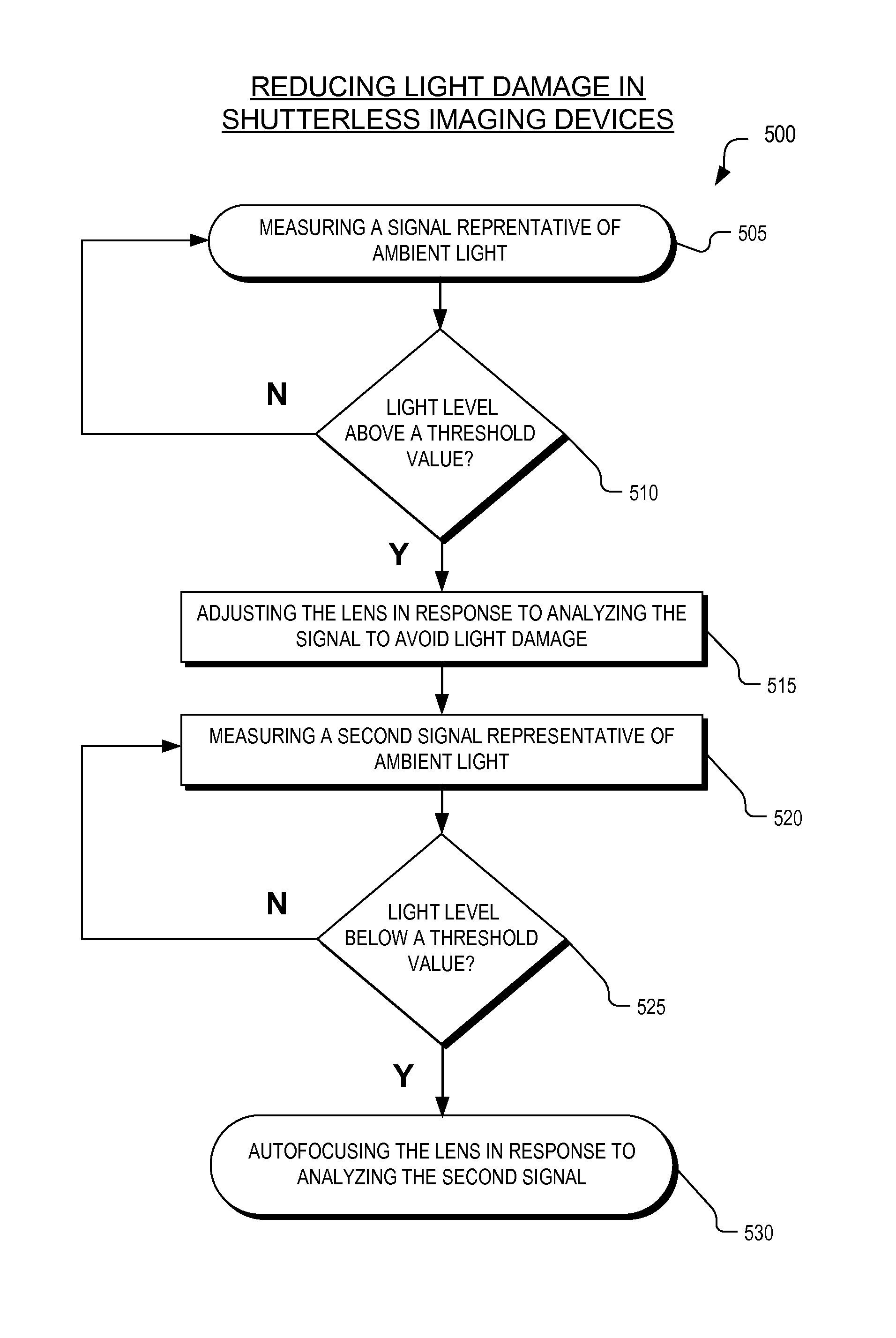
[0012]Embodiments of an apparatus and method for protecting a shutterless imaging device from light damage are described herein. In the following description, numerous specific details are set forth to provide a thorough understanding of the embodiments. One skilled in the relevant art will recognize, however, that the techniques described herein can be practiced without one or more of the specific details, or with other methods, components, materials, etc. In other instances, well-known structures, materials, or operations are not shown or described in detail to avoid obscuring certain aspects.

[0013]Reference throughout this specification to “one embodiment” or “an embodiment” means that a particular feature, structure, or characteristic described in connection with the embodiment is included in at least one embodiment of the present invention. Thus, the appearances of the phrases “in one embodiment” or “in an embodiment” in various places throughout this specification are not nece...


PUM


Abstract

A method of reducing light damage in a shutterless imaging device includes receiving a signal from a hardware device. The signal from the hardware devices is analyzed. In response to the analysis of the signal from the hardware device, a lens of the shutterless imaging device is adjusted. Adjusting the lens spreads out energy of far-field image light incident on an image sensor of the shutterless imaging device.

Description

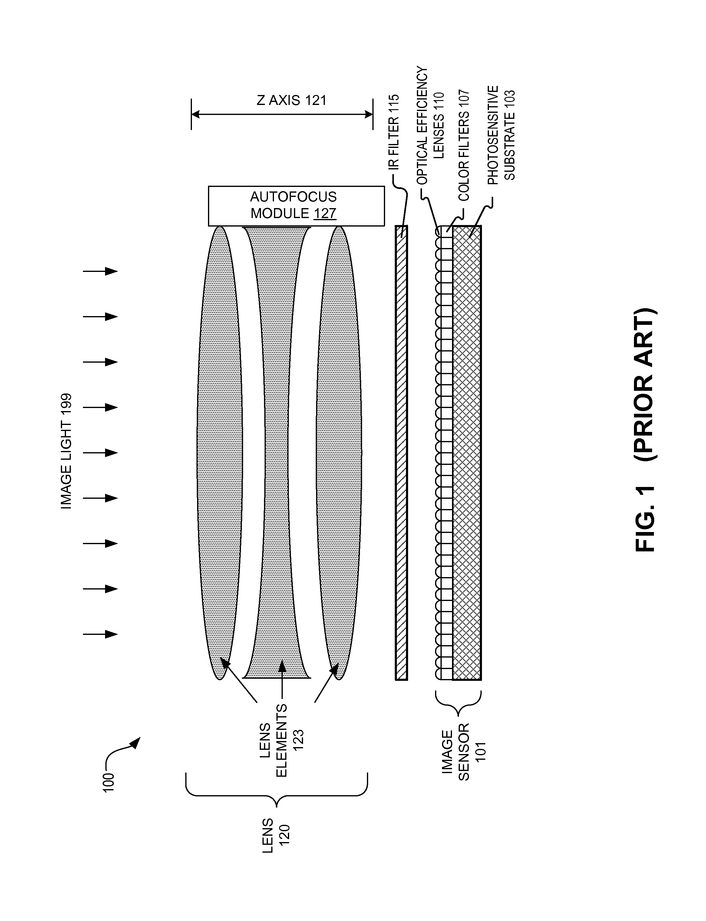
TECHNICAL FIELD[0001]This disclosure relates generally to optics, and in particular but not exclusively, relates to protecting image sensors from light damage.BACKGROUND INFORMATION[0002]Conventional digital imaging devices or cameras have a lens (which may include multiple lens elements) that focuses image light onto an image sensor that measures the image light and generates an image based on the measurements. FIG. 1 illustrates a common configuration for a digital imaging device 100. FIG. 1 includes an image sensor 101 including optical efficiency lenses 110 disposed over photosensitive substrate 103. Optical efficiency lenses 110 function to draw as much light as possible into the pixels for measurement. Optical efficiency lenses 110 may be microlenses disposed over each pixel of image sensor 101. An infrared (“IR”) filter 115 may be disposed over optical efficiency lenses 110 to filter out IR light from being measured by image sensor 101. Color filters 107 may filter out certai...

Claims


Application Information

Patent Timeline
Patent Type & Authority Patents(United States)
IPC IPC(8): H04N5/235H04N5/225H04N5/228H04N9/73G03B9/70H04N5/353
CPCH04N5/353H04N23/67H04N23/75H04N25/53G02B27/017
Inventor D'AMICO, SAMUEL R.MIAO, XIAOYU
Owner GOOGLE LLC
Learn More