
Encoder

a technology of encoder and encoder, which is applied in the direction of code conversion, multiple input and output pulse circuits, instruments, etc., can solve the problems of slow calculation of the decimal value in the fpga circuit, delay the incremental pulse, and take a long time to calcula

Active Publication Date: 2015-05-19
LEINE & LINDE
View PDF2 Cites 1 Cited by
  • Summary
  • Abstract
  • Description
  • Claims
  • Application Information

AI Technical Summary

Benefits of technology

Enables compact and reliable position detection on large shafts with axial play, providing a long service life and facilitating maintenance in challenging environments by eliminating mechanical wear and allowing non-contact detection.

Problems solved by technology

In a wind power station, the encoder may be mounted to detect the movement of the rotating shaft at the high altitude of a wind power tower, making it difficult for maintenance personnel to reach the encoder for maintenance purposes.
However, when the first magneto-electric transducer head passes over a scale edge the sum of the squares becomes lower, which may be due to the magnetic field becoming weaker in the gap portion of the scale.
Unfortunately, it may be slow to calculate that many decimals in an FPGA circuit.
However, if the pulse rate is something else, it could take some time to calculate which will delay the incremental pulse.
It may also be difficult to implement a division in an FPGA circuit with the large number of bits that is needed in order to represent a sufficient number of decimals.

Method used


Image

  • Encoder
  • Encoder
  • Encoder

Examples


Embodiment Construction

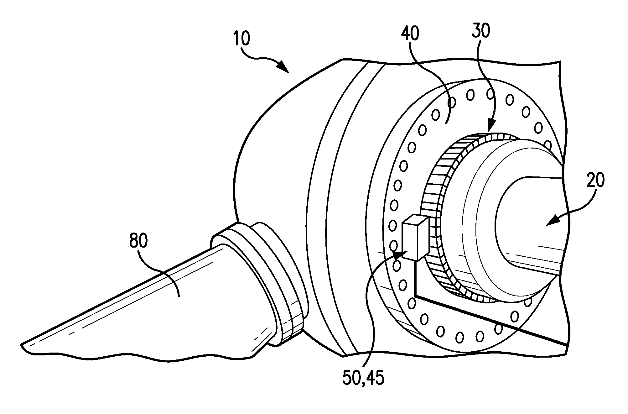
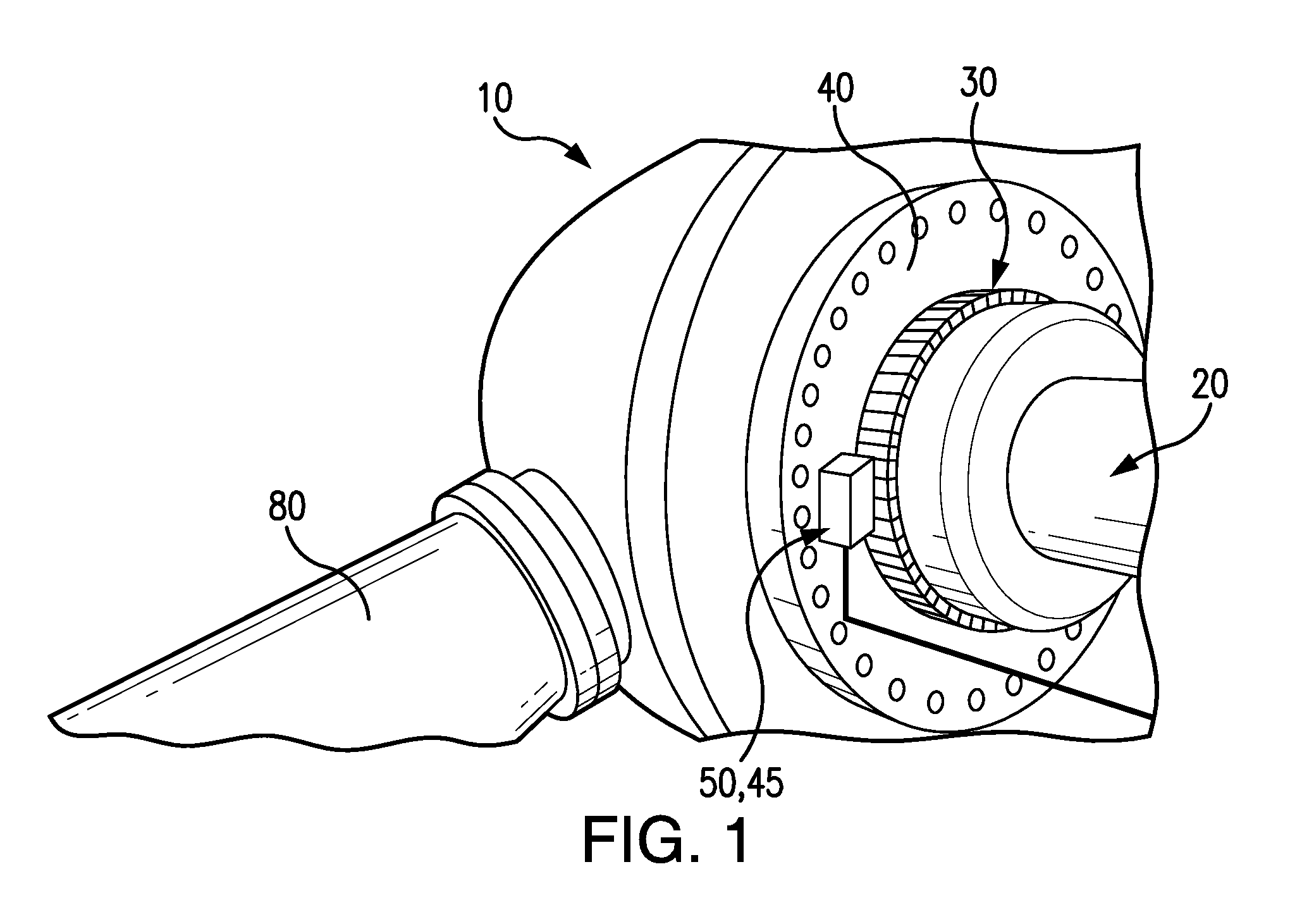
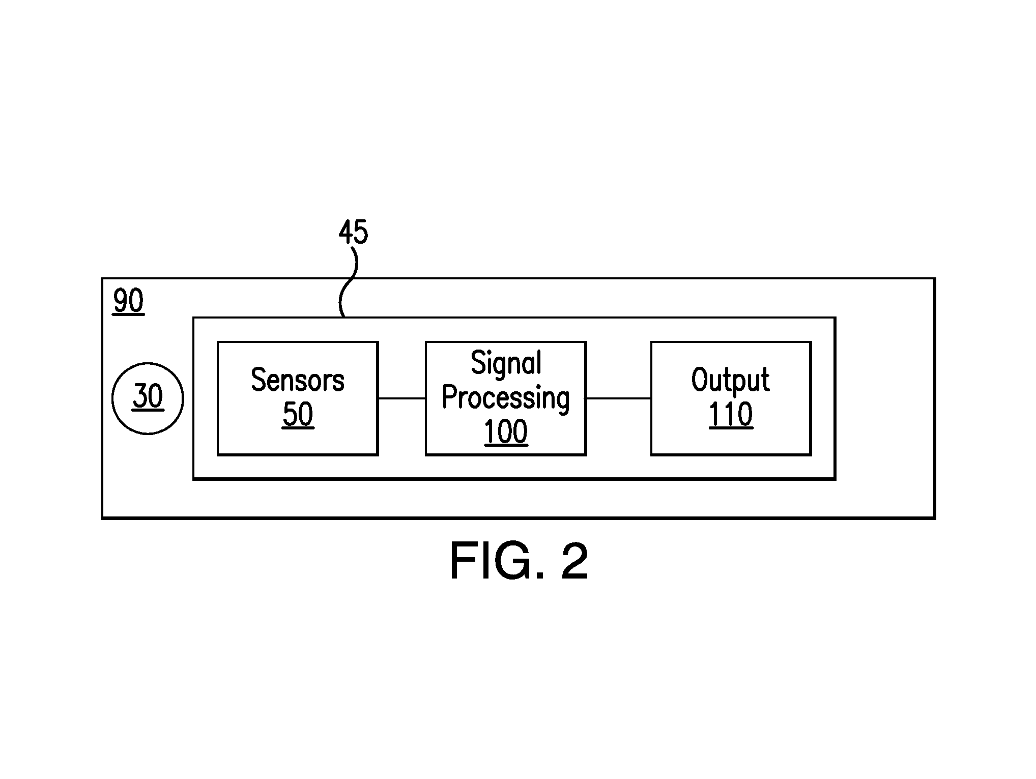
[0163]FIG. 1 is a block diagram illustrating a machine 10 having a rotatable shaft 20. A scale device 30 may be fastened to the shaft 20 so that the scale device 30 moves when the rotatable shaft 20 rotates in relation to a machine part 40. A signal generator 45 may be attachable to the machine part 40. The signal generator 45 may be adapted to generate a signal indicative of a position of the scale device 30 in relation to the signal generator 45, and / or a signal indicative of a relative change in position between the signal generator 45 and the scale device 30.

[0164]The machine 10 may be arranged in a wind power station 10, as illustrated in FIG. 1. Hence, the shaft 20, of the wind power station 10, may be attached to one or more turbine / rotor blades 80 adapted to cause rotation of the shaft 20 in response to air movement caused by wind so as to generate electric power by a generator coupled to the shaft 20. The wind power station may be a geared wind power station, a direct drive...


PUM


Abstract

An encoder is configured for detection of rotational movement of a rotatable shaft in relation to a part of a machine, and a method is provided for generating a reference signal by an encoder.

Description

CROSS-REFERENCE TO RELATED APPLICATIONS[0001]The present application claims priority to Application No. 1200406-5, filed in the Kingdom of Sweden on Jul. 2, 2012, which is expressly incorporated herein in its entirety by reference thereto.[0002]The present application claims the benefit of U.S. Provisional Patent Application No. 61 / 713,801, filed on Oct. 15, 2012, which is expressly incorporated herein in its entirety by reference thereto.FIELD OF THE INVENTION[0003]The present invention relates to an encoder apparatus. The present invention also relates to a method of operating such an encoder apparatus, and to a computer program product for causing an encoder to execute functions.BACKGROUND INFORMATION[0004]In many industrial applications there is a need to monitor the movement of a movable part. Such monitoring requires the delivery of an encoder output signal indicative of the movement, or indicative of the position of the movable part.[0005]It is conventional to provide an enco...

Claims


Application Information

Patent Timeline
Patent Type & Authority Patents(United States)
IPC IPC(8): G01D5/244G01B7/30G01D5/14G01D5/20
CPCG01D5/244G01D5/145G01D5/2073H03K5/24H03M1/485
Inventor GUSTAFSSON, FREDRIKKJELLQVIST, LARS PETER JOHAN
Owner LEINE & LINDE
Learn More