Electrode for capillary electrophoresis

Active Publication Date: 2015-05-19
WANG TIANSONG
View PDF1 Cites 2 Cited by
  • Summary
  • Abstract
  • Description
  • Claims
  • Application Information

AI Technical Summary

Problems solved by technology

I have found that prior-art electrode designs did not perform optimally si

Method used


Image

  • Electrode for capillary electrophoresis
  • Electrode for capillary electrophoresis
  • Electrode for capillary electrophoresis

Examples


Example

First Embodiment—FIGS. 3 Through 5

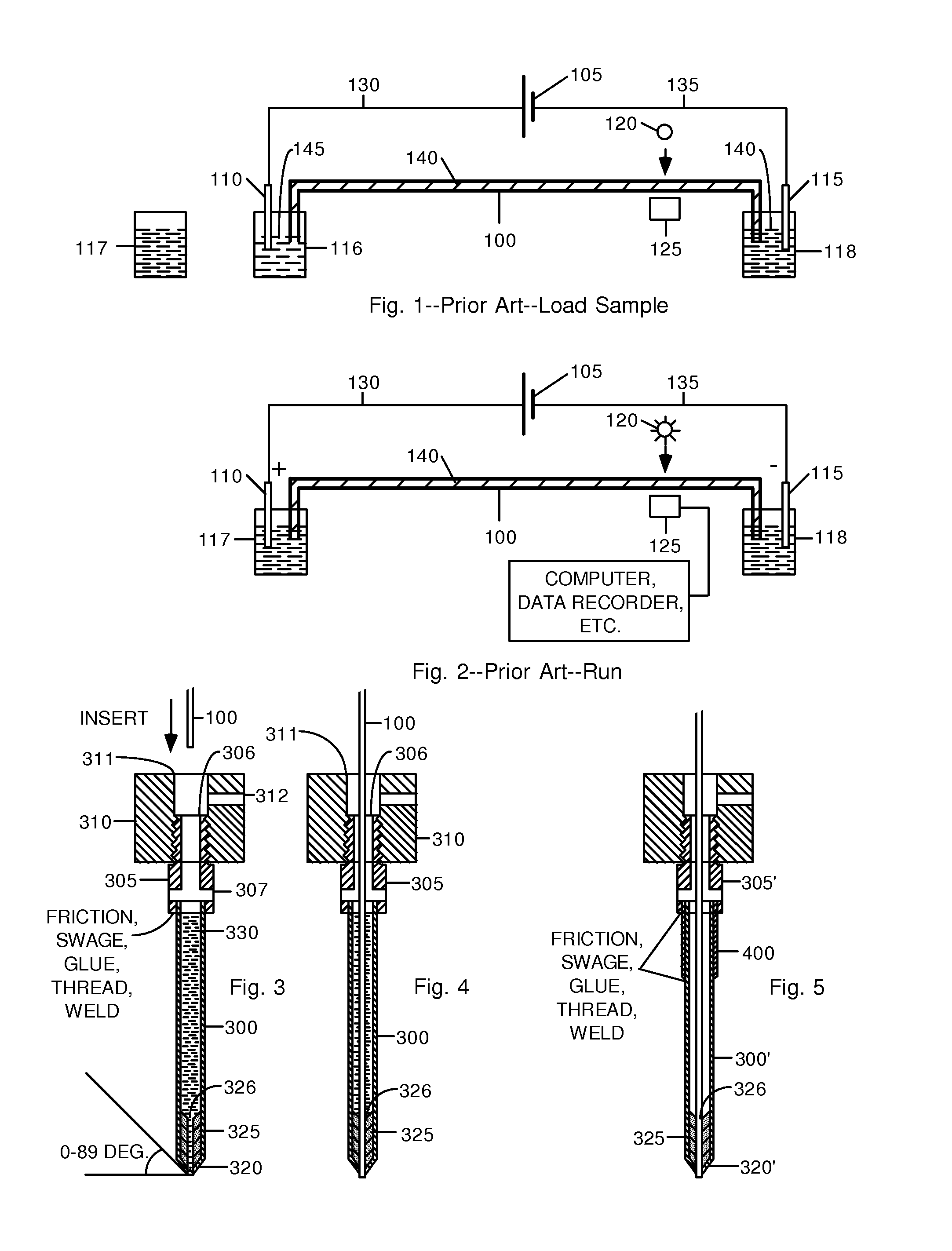
[0027]FIGS. 3 through 5 show sectional side views of two aspects of a first embodiment.

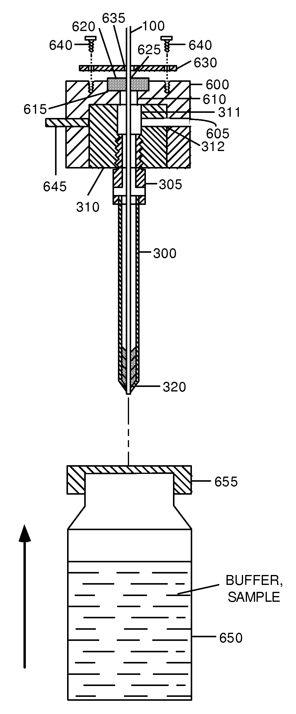
[0028]In the prior-art apparatus of FIGS. 1 and 2, the end of capillary tube 100 is merely positioned below the surface of the contents of containers 116, 117, and 118. In many cases, such containers are sealed at the top by a thin membrane, usually rubber, as described below. The membrane must be pierced so that capillary tube 100 can be inserted into these contents. Capillary tube 100 doesn't have sufficient strength to pierce a membrane by itself and a strengthening element is required. When the prior-art apparatus is in use, Joule heating at the electrodes can cause decomposition of the sample being separated.

[0029]First Aspect.

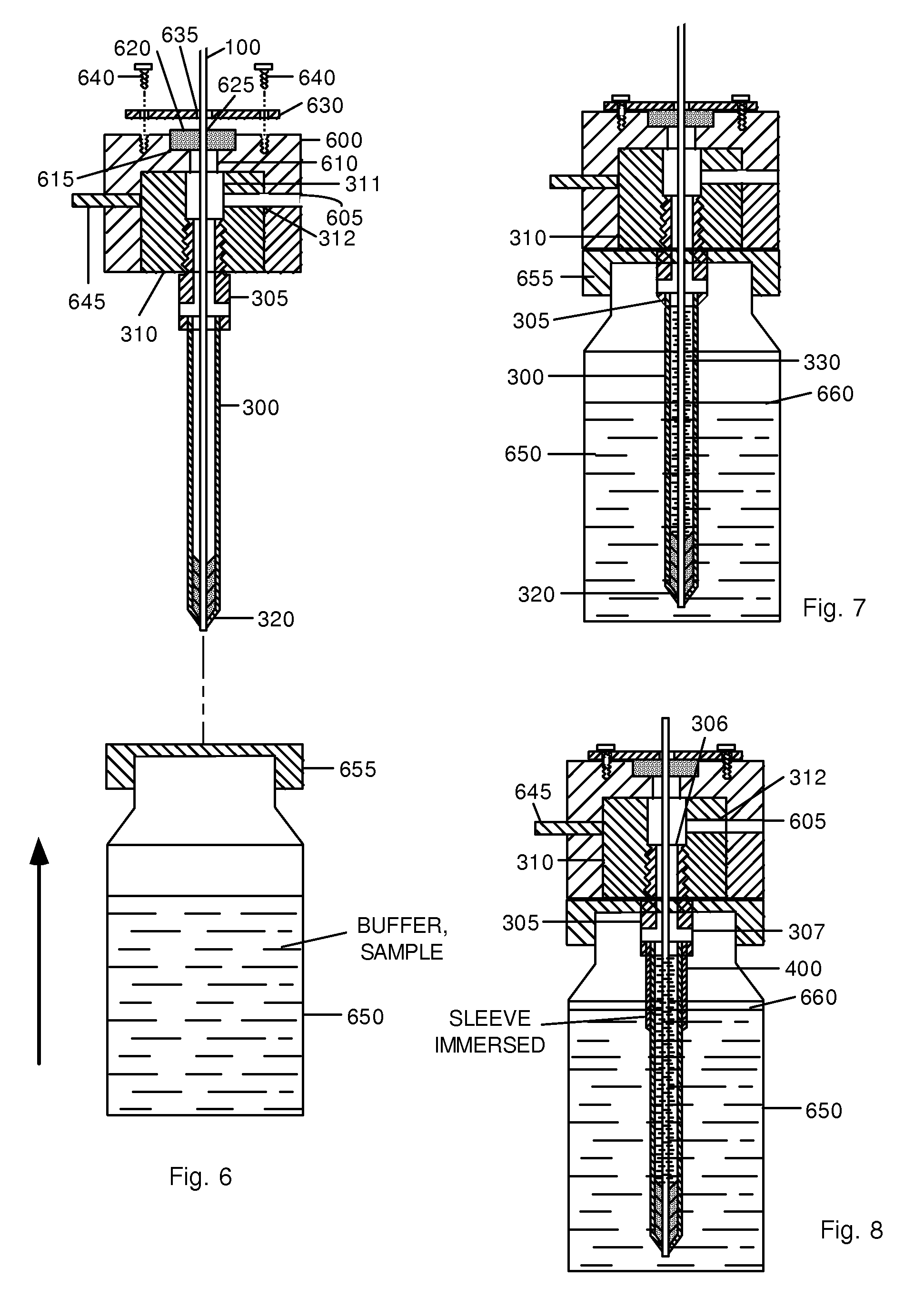
[0030]FIGS. 3 and 4 show a first aspect of a first embodiment of a capillary electrophoresis electrode. Instead of an isolated metal wire electrodes 110 and 115 in FIGS. 1 and 2, a tubular electrode is designed to provide both thermal a...


PUM


Abstract

An electrode assembly for capillary electrophoresis (CE) comprises a manifold (310), a connector (305) a sheath (300), and a seal (325). A capillary tube (100) passes through the manifold, the connector, the sheath, and the seal, stopping just beyond the end of the sheath. The sheath is fillable with water (330) or another fluid that cools the capillary tube in the vicinity of the electrode, thereby preventing degradation of a sample due to heat. The sheath may be metal or plastic with a metal sleeve electrode on its exterior. The sheath is sufficiently strong to penetrate a rubber or other pierceable cap on a vial. The manifold and connector incorporate an air path (605, 312, 307) so that when the electrode is fully inserted into a vial, the contents (650) of the vial are at atmospheric pressure (or another applied pressure or vacuum).

Description

BACKGROUNDPrior Art—Electrophoresis—FIGS. 1-4[0001]Electrophoresis is a powerful and well-known method that is used in many fields of science to separate molecules having different sizes and different intrinsic electrical charges in order to analyze and synthesize chemical compounds. It is used in DNA sequencing, in the separation of mixtures of proteins, and the like. Two principal methods for performing electrophoretic separations are in routine use today, the planar gel matrix and capillary electrophoresis. These will now be discussed.Planar Gel Matrix:[0002]In this method a planar gel matrix (flat body of a gel), such as agarose (a complex carbohydrate polysaccharide obtained from agar), is provided and electrodes are located at opposite edges of the gel. A mixture of ionized, i.e., charged, molecules of a substance to be analyzed is applied or positioned in the gel near a first electrode at one edge of the gel, and an DC electrical potential is applied to the electrodes. Becaus...

Claims


Application Information

Patent Timeline
IPC IPC(8): G01N27/403G01N27/447
CPCG01N27/44756G01N27/44708G01N27/447
Inventor WANG, TIANSONG
Owner WANG TIANSONG
Why Eureka
Try Eureka