
Table cleaning implement

a technology for cleaning implements and tables, applied in the field of cleaning implements, can solve the problems of long waiting period, heavy burden on restaurant personnel, dissatisfaction of waiting customers, etc., and achieve the effects of reducing the time spent cleaning the floor, the surrounding area, and reducing the time spent cleaning

Inactive Publication Date: 2015-05-19
RICHARDSON RICH L
View PDF24 Cites 2 Cited by
  • Summary
  • Abstract
  • Description
  • Claims
  • Application Information

AI Technical Summary

Benefits of technology

The present table cleaning implement has several technical advantages. It reduces the time a table remains unoccupied due to cleaning and resetting, allowing for efficient and thorough bussing, cleaning, and resetting of tables. Additionally, it reduces the time spent cleaning the floor, chairs, and surrounding area, utilizing a broom and sweeper. The implement is constructed of lightweight materials, easy to handle with one hand, hand washable, dishwasher safe, and can be easily stored or hung when not in use. The technical effects are simple construction, inexpensive manufacture, and reliable and effective use.

Problems solved by technology

Thus, there is a heavy burden on restaurant personnel, including the waitresses, and the “busser” (busboy or busgirl), to make sure that no table remains unoccupied any longer than absolutely necessary due to cleaning and resetting the table, known as “bussing”.
Inefficiency in accomplishing the table cleaning and resetting or bussing task results in longer waiting periods for customers, and can cause dissatisfaction of waiting customers.
Although care may be taken by the busser, crumbs and debris may fall onto the chair seats and surrounding area, and time is consumed by having to sweep the loor and surrounding area.

Method used


Image

  • Table cleaning implement
  • Table cleaning implement
  • Table cleaning implement

Examples


Embodiment Construction

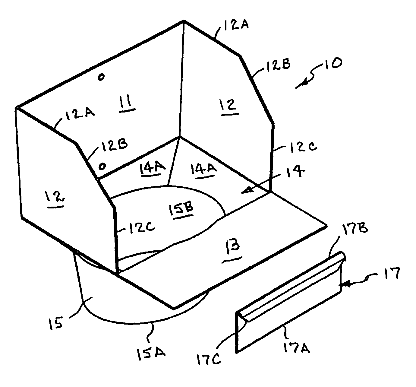
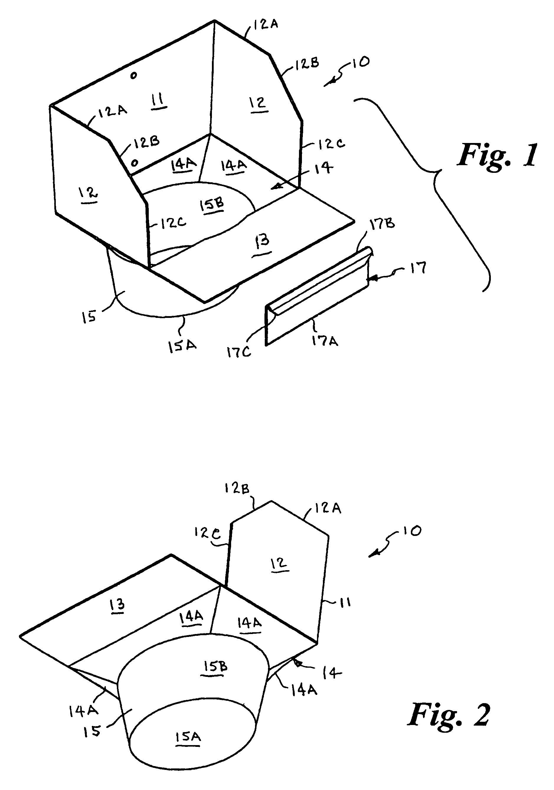
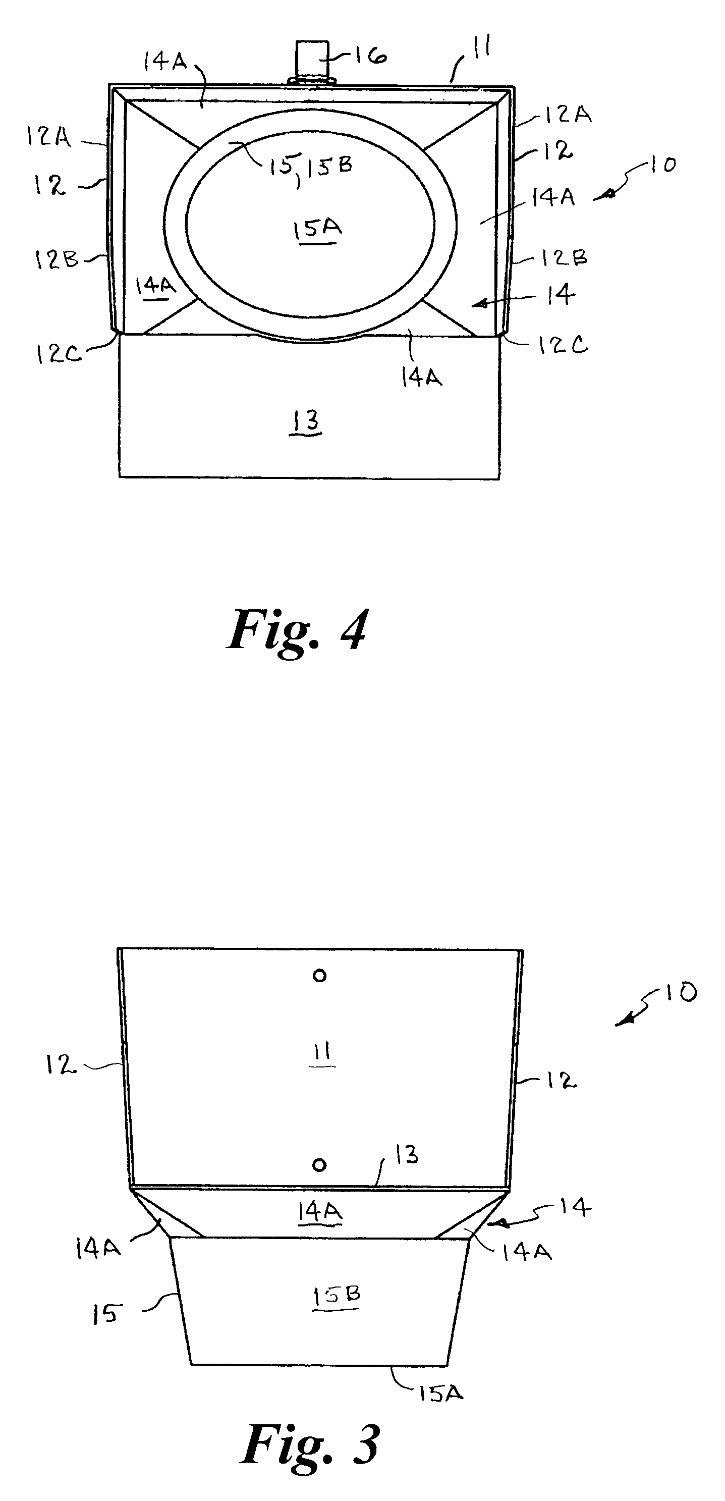
[0027]Referring to the drawings by numerals of reference, there is shown in FIGS. 1-6, a preferred table cleaning implement 10 formed of a rigid material such as molded plastic or metal. The table cleaning implement 10 has a three-sided upper portion formed of an upstanding rear wall 11 and adjoined upstanding lateral side walls 12 that extend forwardly from the rear wall 11. Each lateral side wall 12 has a horizontal top end portion 12A that extends forwardly a distance from the rear wall 11, a diagonal portion 12B that extends angularly downward and forward therefrom and terminates in a vertical front end 12C.

[0028]A flat planar generally rectangular horizontal platform 13 extends transversely between the bottoms of the front ends 12C of the lateral side walls 12 and a distance forwardly therefrom and terminates in a front end.

[0029]The table cleaning implement 10 has an intermediate portion 14 that extends downwardly and inwardly from the upper portion. In the illustrated example...


PUM


Abstract

A hand-held table cleaning implement has upstanding rear and laterally opposed side walls, a handle on the backside of the rear wall, a flat horizontal platform extending a distance forwardly from the side walls for insertion beneath a table top, an intermediate portion adjoined to bottom ends of the rear and side walls and back end of the platform defining a central opening tapering downwardly and inwardly therefrom, and a trash receptacle extending downwardly from the intermediate portion for receiving trash, refuse, crumbs, and debris swept or scraped from the table top surface. A generally rectangular scraper may be provided that can be clipped onto a flat surface of the table cleaning implement, and removed therefrom for use in scraping and sweeping debris, crumbs, and food remnants from the table top and into the receptacle. The implement can be hooked over an edge of another object, and is easily stored.

Description

BACKGROUND OF THE INVENTION[0001]1. Field of the Invention[0002]This invention relates generally to cleaning implements and, more particularly, to a hand-held table cleaning implement having a flat horizontal platform portion with upstanding rear and laterally opposed side walls, a front portion extending forwardly therefrom for insertion beneath a table top, and a trash receptacle extending downwardly from the platform for receiving trash, refuse, crumbs, and debris swept or scraped from the table surface.[0003]2. Background Art[0004]It is important for restaurants, cafeterias, and other dining establishments to minimize the amount of time that each table is unoccupied, especially during certain busy periods, such as lunch periods, dinner periods and weekend evenings. Thus, there is a heavy burden on restaurant personnel, including the waitresses, and the “busser” (busboy or busgirl), to make sure that no table remains unoccupied any longer than absolutely necessary due to cleaning...

Claims


Application Information

Patent Timeline
Patent Type & Authority Patents(United States)
IPC IPC(8): A47B85/00A47B13/00
CPCA47B13/00A47F13/08B65F1/02B65F1/10
Inventor RICHARDSON, RICH L.
Owner RICHARDSON RICH L
Learn More