
Content delivery system with allocation of source data and repair data among HTTP servers

a content delivery system and source data technology, applied in the field of encoding and decoding data in communications systems, can solve the problems of low computational complexity of chain reaction encoding and decoding process, source data might not be entirely recoverable, and relatively computationally intensiv

Inactive Publication Date: 2015-04-21
QUALCOMM INC
View PDF21 Cites 19 Cited by
  • Summary
  • Abstract
  • Description
  • Claims
  • Application Information

AI Technical Summary

Benefits of technology

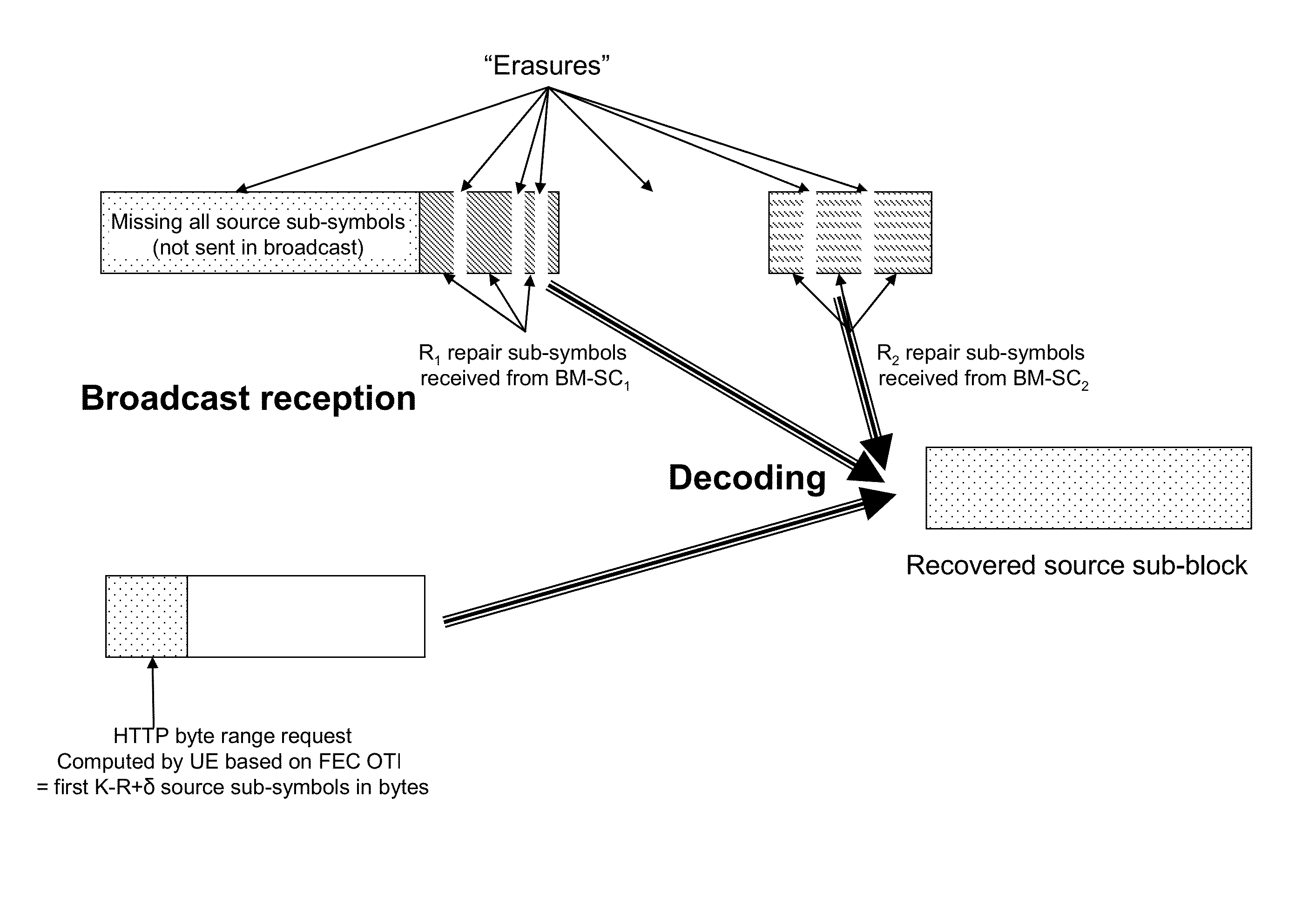
[0048]In some cases, the request to the unicast server is in the form of an HTTP byte-range request. Where an HTTP byte-range request specifies a URL of a file, a starting position in the file and a length of the request (such as the number of symbols requested), or the number of sub-symbols requested, or a byte range request corresponding to a consecutive set of sub-symbols or symbols), the requests might be such that all or many of the requests use the initial position of the file as the starting position. This would allow for downstream caches to more frequently fulfill requests, as it would have all the necessary data to provide, once it has cached the largest request with respect to a given file, since all smaller requests would be a subset of that cached byte range.

Problems solved by technology

Lost data (erasures) are often easier to deal with than corrupted data (errors) because the recipient cannot always tell when corrupted data is data received in error.
In a simple case, the encoded data is a copy of the source data, but if the received encoded data differs (due to errors and / or erasures) from the transmitted encoded data, in this simple case the source data might not be entirely recoverable absent additional data about the source data.
However, they can be fairly computationally intensive at times. A decoder might be able to decode more often, or more easily, if the source symbols are encoded using a static encoder prior to a dynamic encoder that encodes using a chain reaction or another rateless code.
Preferably, the computational complexity of performing chain reaction encoding and decoding processes is low.
In a typical system, a brute force implementation of this can consume excessive computing effort and memory requirements.
Of course, for a particular set of received encoded symbols, it might be impossible to recover all of the original input symbols, but even where it is possible, it might be very computationally expensive to compute the result.
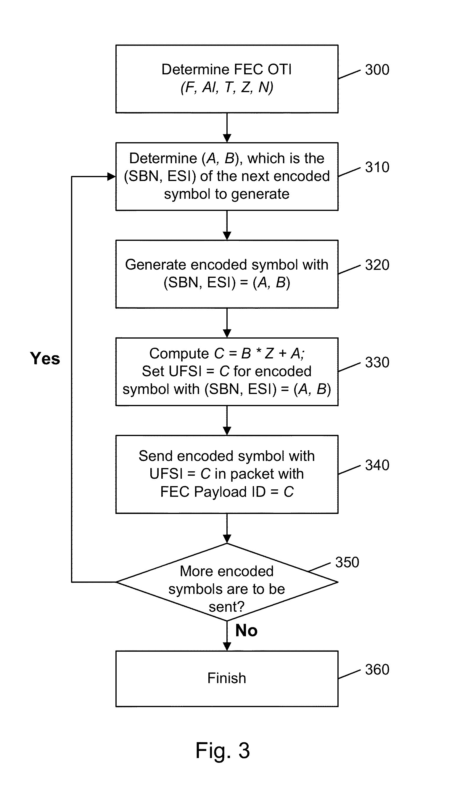
One disadvantage of this FEC Payload ID format is that one has to pre-determine the number of bits of the FEC Payload ID to allocate to the SBN and to the ESI, and it is sometimes difficult to determine a proper mix that will be adequate for all file delivery parameters.
However, there are drawbacks to this approach.
For example, it is not desirable to have to modify the FEC code itself to provide UEP, as this complicates implementing and testing the FEC code itself Furthermore, as the results shown in FIG. 6 of [LDPC-Extensions], the resulting performance of such an approach in terms of the resiliency to packet loss that is provided for the different parts of the file is far from optimal.
This is very difficult to support using an FEC Payload ID of the format (SBN, ESI), as for each part of the file the corresponding SBN and ESI for the symbol in the packet for a first part of the file might be different than the SBN and ESI for the symbol in the packet for a second part of the file.
In some cases, specialized servers are required, and that can be more expensive to implement, support and maintain that using more common, conventional hardware systems to support content deliver.

Method used


Image

  • Content delivery system with allocation of source data and repair data among HTTP servers
  • Content delivery system with allocation of source data and repair data among HTTP servers
  • Content delivery system with allocation of source data and repair data among HTTP servers

Examples


Embodiment Construction

[0092]In embodiments herein, file delivery is performed by an encoder / transmitter system that sends a file and a receiver / decoder system that receives a file. The format of the transmissions is coordinated so that the decoder understands what the encoder encoded. As shown in various examples below, file delivery is an example of general object delivery and unless otherwise indicated, it should be apparent from these examples that objects can be treated as files and possibly vice versa.

[0093]In a packet delivery system, the data is organized into packets and transmitted as packets. Each packet has elements that allow a receiver to determine what is in the packet and how it is laid out. Using the techniques described herein, flexibility is provided for transmitting packets where forward error correction (“FEC”) is used.

[0094]Using these techniques, unequal FEC protection can be provided, as well as bundled delivery of files. It is well-known that when many files are delivered as separ...


PUM


Abstract

Data objects are delivered over a packet-switched network and receivers receive encoded symbols, such as repair symbols, broadcast or multicast, with sufficient information to form requests for additional symbols as needed based on what source symbols or sub-symbols are needed or missing. The requests can be made in a unicast or request fashion. Requesting and broadcasting might be done by different entities. A broadcast server can generate and store repair symbols while a source server can store content in source form. A request can be a unicast HTTP byte-range request, such as a URL, starting position and length. Requests might be aligned with starting positions of files. A receiver can calculate starting and ending byte positions of symbols or sub-symbols in a file and get indications that conventional HTTP servers are usable for file repair. Repair servers can request broadcast of repair data when byte-range requests from multiple receivers overlap.

Description

CROSS-REFERENCE TO RELATED APPLICATIONS[0001]This application claims priority from and is a non-provisional of U.S. Provisional Patent Application No. 61 / 614,408, filed Mar. 22, 2012 entitled “Unicast Repair Service and Server Augmenting Broadcast File Delivery System”, U.S. Provisional Patent Application No. 61 / 645,562, filed May 10, 2012 entitled “Content Delivery System with Allocation of Source Data and Repair Data Among HTTP Servers”, and U.S. Provisional Patent Application No. 61 / 647,414, filed May 15, 2012 entitled “Content Delivery System with Allocation of Source Data and Repair Data Among HTTP Servers”, the entire disclosure of which is incorporated by reference herein for all purposes.[0002]The present disclosure may be related to the following commonly assigned patents or applications, each of which are herein incorporated by reference in their entirety for all purposes:[0003]1) U.S. Pat. No. 6,307,487 issued to Michael G. Luby, entitled “Information Additive Code Genera...

Claims


Application Information

Patent Timeline
Patent Type & Authority Patents(United States)
IPC IPC(8): H03M13/00H03M13/35H03M13/37H04L1/18
CPCH03M13/356H03M13/3761H03M13/6306H04L1/1819H04L65/611H04L1/0045H04L67/02
Inventor LUBY, MICHAEL GEORGELEUNG, NIKOLAI KONRADGHOLMIEH, RALPH AKRAMSTOCKHAMMER, THOMAS
Owner QUALCOMM INC
Learn More