
Electronic device and support mechanism thereof

a technology of support mechanism and electronic device, which is applied in the direction of portable computer details, electric apparatus casings/cabinets/drawers, instruments, etc., can solve the problems of increasing manufacturing costs, increasing the complexity of electronic devices, and difficulty for users to hold electronic devices

Active Publication Date: 2015-04-21
WISTRON CORP
View PDF87 Cites 26 Cited by
  • Summary
  • Abstract
  • Description
  • Claims
  • Application Information

AI Technical Summary

Benefits of technology

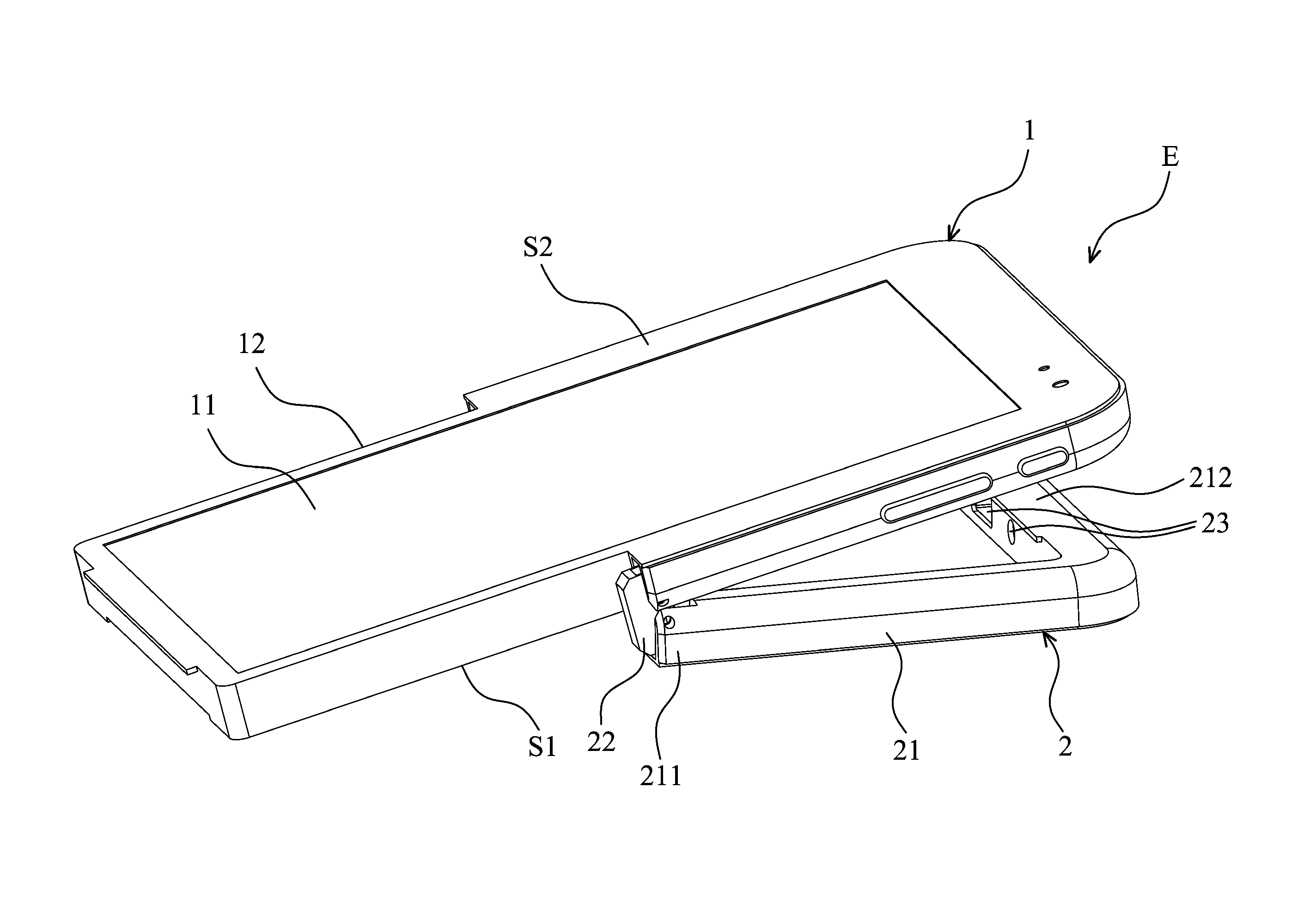
[0006]An embodiment of the invention provides an electronic device, comprising a main body, and a support mechanism. The main body forms a U-shaped recess, and the support mechanism comprises a U-shaped support, two pivot members, and an electrical connection port. The U-shaped support forms two ends, the two pivot members pivotally connect the two ends to the main body, respectively, and the electrical connection port is disposed on the support. When the support is in a closed angle position that is relative to the main body, the support is received in the recess and parallel to the main body, and the electrical connection port is covered by the main body. When the support is rotated relative to the main body and is released from the recess, the electrical connection port is exposed to a surface of the support.

Problems solved by technology

Since the electronic devices have streamlined appearances and smooth surfaces, it is difficult for users to hold the electronic devices.
Additional frames may be provided to support the electronic devices on a surface, but they may increase manufacturing costs and structural complexity of the electronic devices.

Method used


Image

  • Electronic device and support mechanism thereof
  • Electronic device and support mechanism thereof
  • Electronic device and support mechanism thereof

Examples


Embodiment Construction

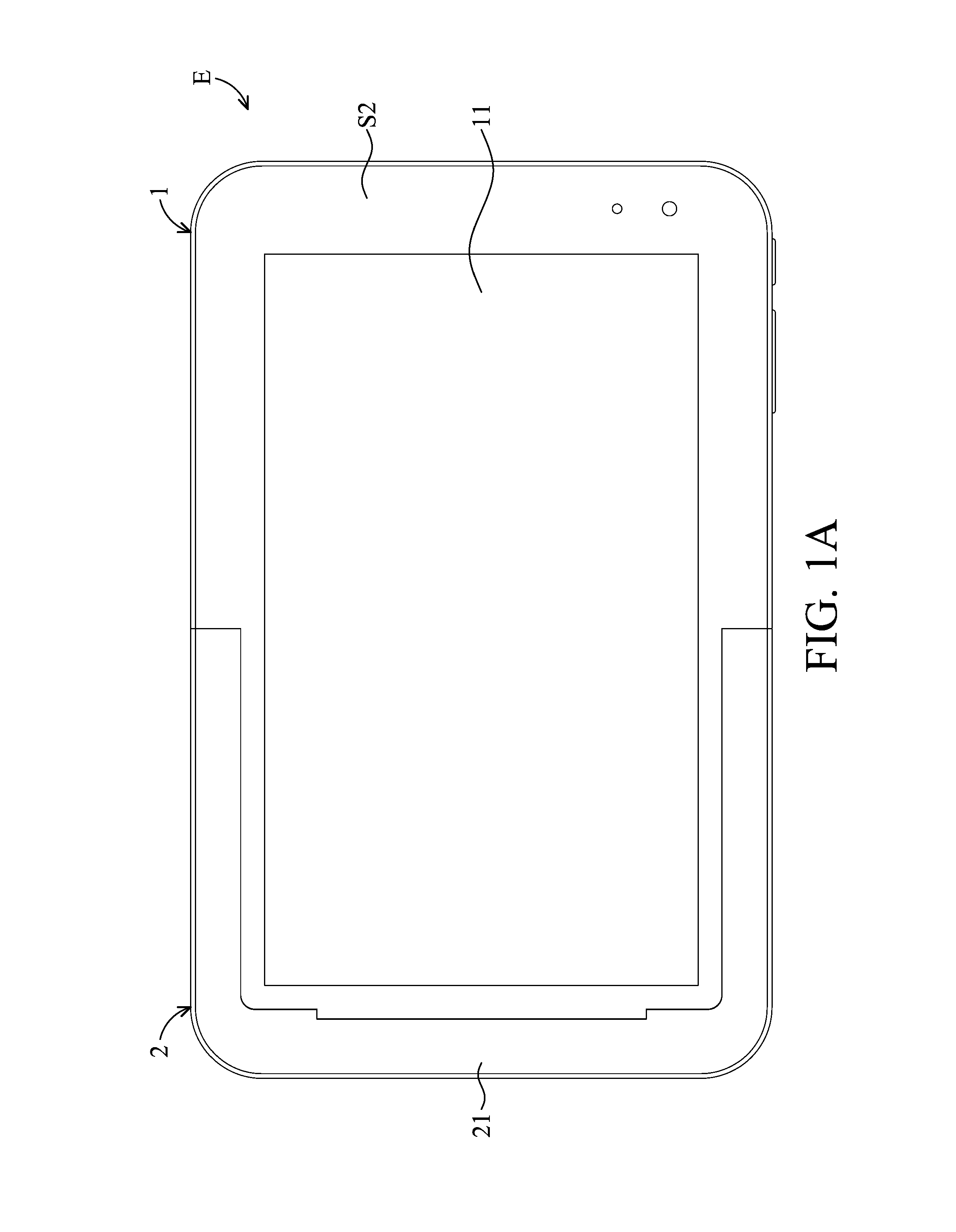
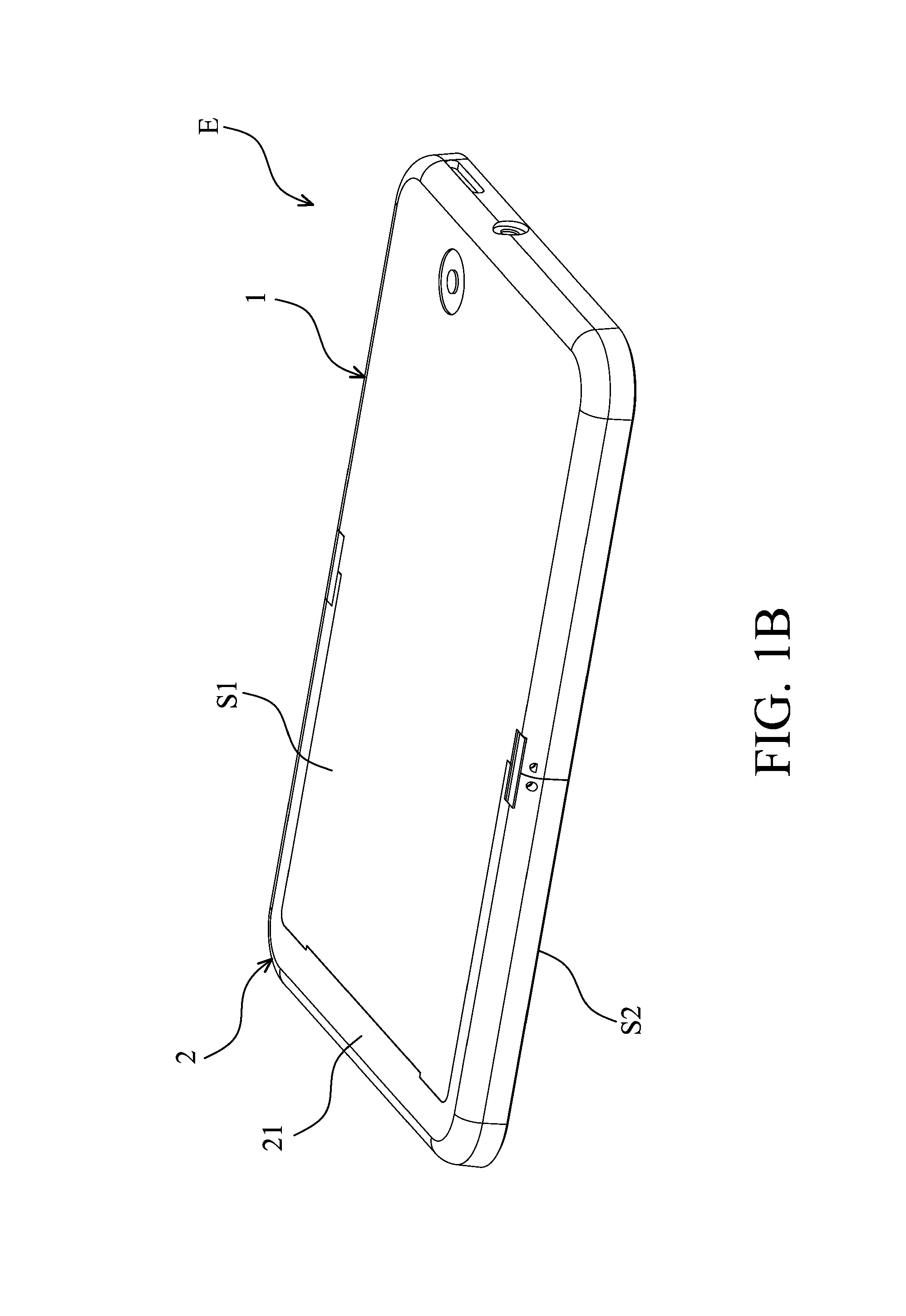
[0013]Referring to FIGS. 1A-3, an embodiment of an electronic device E, such as a tablet PC or a mobile communication device, primarily comprises a main body 1 and a support mechanism 2. The main body 1 forms a U-shaped recess 12 (FIGS. 2A and 2B) and has a display module 11 with a touch screen. The support mechanism 2 comprises an approximately U-shaped support 21 corresponding to the U-shaped recess 12, and the support 21 is pivotally connected to opposite sides of the main body 1 and rotatable relative to the main body 1.

[0014]As shown in FIGS. 1A and 2A, when the support 21 is in a closed angle position that is relative to the main body 1, the support 21 is received in the U-shaped recess 12 of the main body 1 and parallel thereto. Referring to FIG. 2A, when the support 21 is rotated to an angle that is relative to the main body 1, the support 21 can support the main body 1 to stand on a supporting surface, so that users can conveniently view or operate the electronic device E w...


PUM


Abstract

An electronic device is provided, including a main body and a support mechanism. The main body forms a U-shaped recess. The support mechanism includes a U-shaped support, two pivot members and an electrical connection port. The support forms two ends, and the pivot members rotatably connect the two ends to the main body. The electrical connection port is disposed on the support. When the support is in a closed angle position that is relative to the main body, the support is received in the recess and parallel to the main body, and the electrical connection port is covered by the main body. When the support is rotated relative to the main body and is released from the recess, the electronic device can stand on a surface by the support, and the electrical connection port is exposed to a surface of the support.

Description

CROSS REFERENCE TO RELATED APPLICATIONS[0001]This Application claims priority of Taiwan Patent Application No. 101121691, filed on Jun. 18, 2012, the entirety of which is incorporated by reference herein.BACKGROUND OF THE INVENTION[0002]1. Field of the Invention[0003]The application relates in general to an electronic device, and in particular, to an electronic device having a support mechanism.[0004]2. Description of the Related Art[0005]Most of the conventional portable electronic devices, such as tablet computers or mobile communication devices, can play multimedia content. Users usually have to hold the electronic devices when viewing the content that is displayed. Since the electronic devices have streamlined appearances and smooth surfaces, it is difficult for users to hold the electronic devices. Additional frames may be provided to support the electronic devices on a surface, but they may increase manufacturing costs and structural complexity of the electronic devices.BRIEF ...

Claims


Application Information

Patent Timeline
Patent Type & Authority Patents(United States)
IPC IPC(8): H04M1/04F16M11/10F16M13/00G06F1/16H05K5/02
CPCH05K5/0217F16M11/10F16M13/005H04M1/04G06F1/1626G06F1/166
Inventor CHEN, TSUNG-HSIENCHANG, HSING-WANGHSU, PO-YUANSU, CHIA-CHENGWANG, WEI-CHENG
Owner WISTRON CORP
Learn More