Optical fiber ribbon, optical fiber cable, and wire configuration, each having identification marking

a technology of optical fiber ribbon and identification marking, which is applied in the direction of bundled fibre light guides, instruments, fibre mechanical structures, etc., can solve the problems of limited number of optical fibers that can be identified, number of usable colors, and easy to determine, so as to increase the type and number of optical fibers, easy to identify optical fiber ribbons, and good identification

Active Publication Date: 2015-04-14
FUJIKURA LTD
View PDF12 Cites 12 Cited by
  • Summary
  • Abstract
  • Description
  • Claims
  • Application Information

AI Technical Summary

Benefits of technology

[0013]Accordingly, the present invention has been made in the light of the aforementioned circumference, and an object of the present invention is to provide an optical fiber ribbon including a plurality of optical fibers joined in parallel, the optical fiber ribbon allowing good identification of a number of types of optical fiber tape cores without degradation of identification due to deterioration over time and allowing identification of optical fibers when the tape material is removed to use the individual optical fibers and to provide an optical fiber cable including the aforementioned optical fiber ribbons, and a wire configuration.
[0017]According to the present invention, it is easy to identify the optical fiber ribbons. Moreover, by changing the colors, arrangement, shapes, and the like due to the combinations of the color layers and the markings provided for the optical fibers, the types and number of optical fibers can be increased with the good identification being maintained. Furthermore, the markings are provided under the color layers, and the identification cannot be therefore damaged by deterioration over time. Still furthermore, since the markings have good visibility and distinguishability, the color of each optical fiber (the color of each color layer) can be easily identified. Still furthermore, even if the tape materials are removed from the optical fibers, the markings and color layers remain, and the optical fibers can be therefore easily identified.

Problems solved by technology

Meanwhile, in the case of coloring the surfaces of the optical fibers of the aforementioned conventional optical fiber ribbon, the number of usable colors is limited, and accordingly, a limited number of optical fibers can be identified.
Even if intermediate colors are used, it is not easy to determine such intermediate colors, and therefore identification of the optical fibers is difficult.
Moreover, even if the optical fibers are identified by combinations of colors, such identification is also difficult.
This makes it difficult to provide good identification.
In the case of providing markings on the surfaces of the tape materials, the markings deteriorate over time due to the temperature, humidity, and the like, thus resulting in degradation of identification.
Furthermore, in the optical fiber ribbon, if the positions of the markings are distributed in the longitudinal direction, the combinations of the markings are difficult to distinguish, thus degrading the identification.

Method used


Image

  • Optical fiber ribbon, optical fiber cable, and wire configuration, each having identification marking
  • Optical fiber ribbon, optical fiber cable, and wire configuration, each having identification marking
  • Optical fiber ribbon, optical fiber cable, and wire configuration, each having identification marking

Examples


examples

Examples of Optical Fiber Ribbon

[0042]FIG. 6 is plan views showing configurations of Examples of the optical fiber ribbon according to the embodiment.

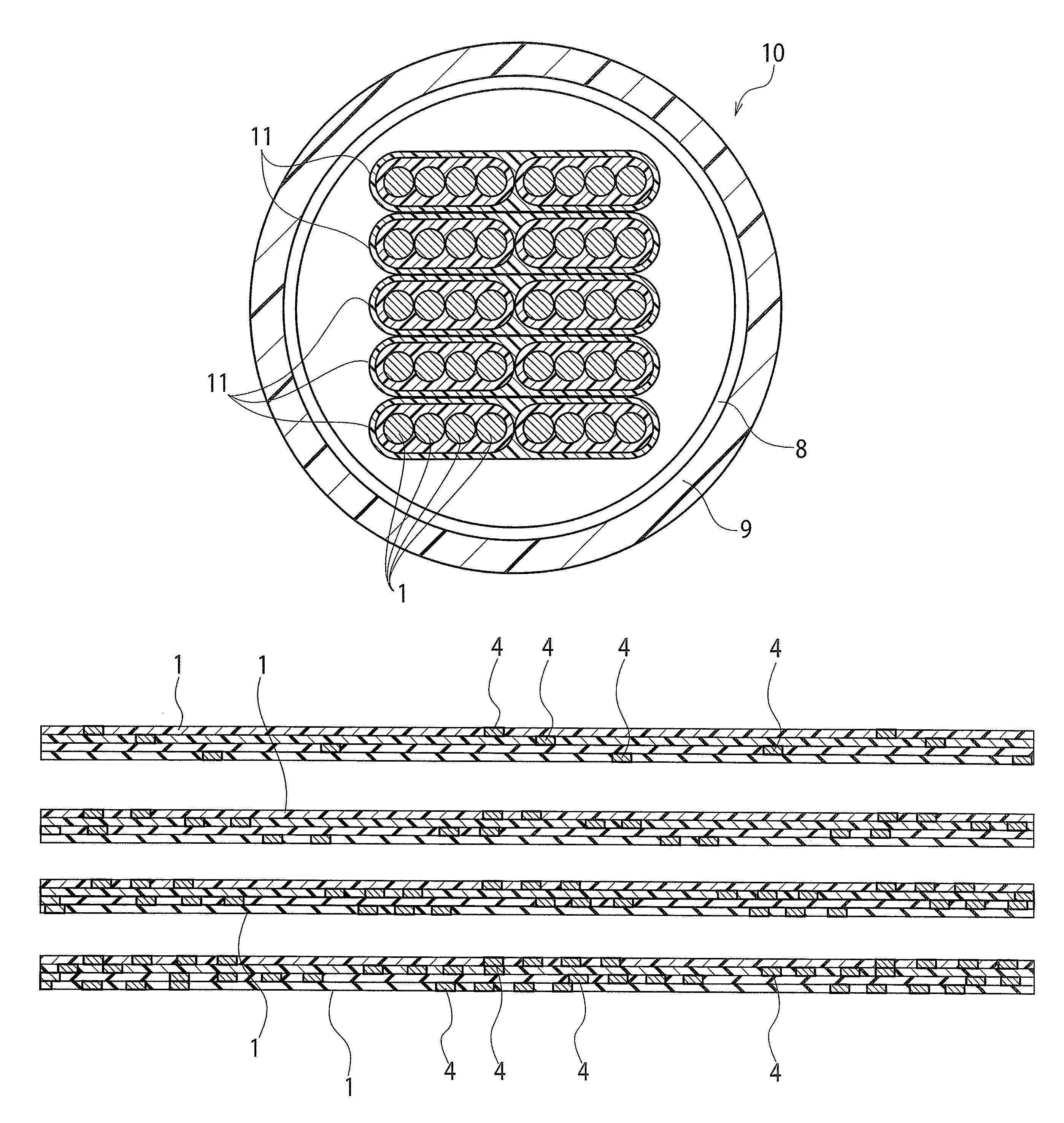
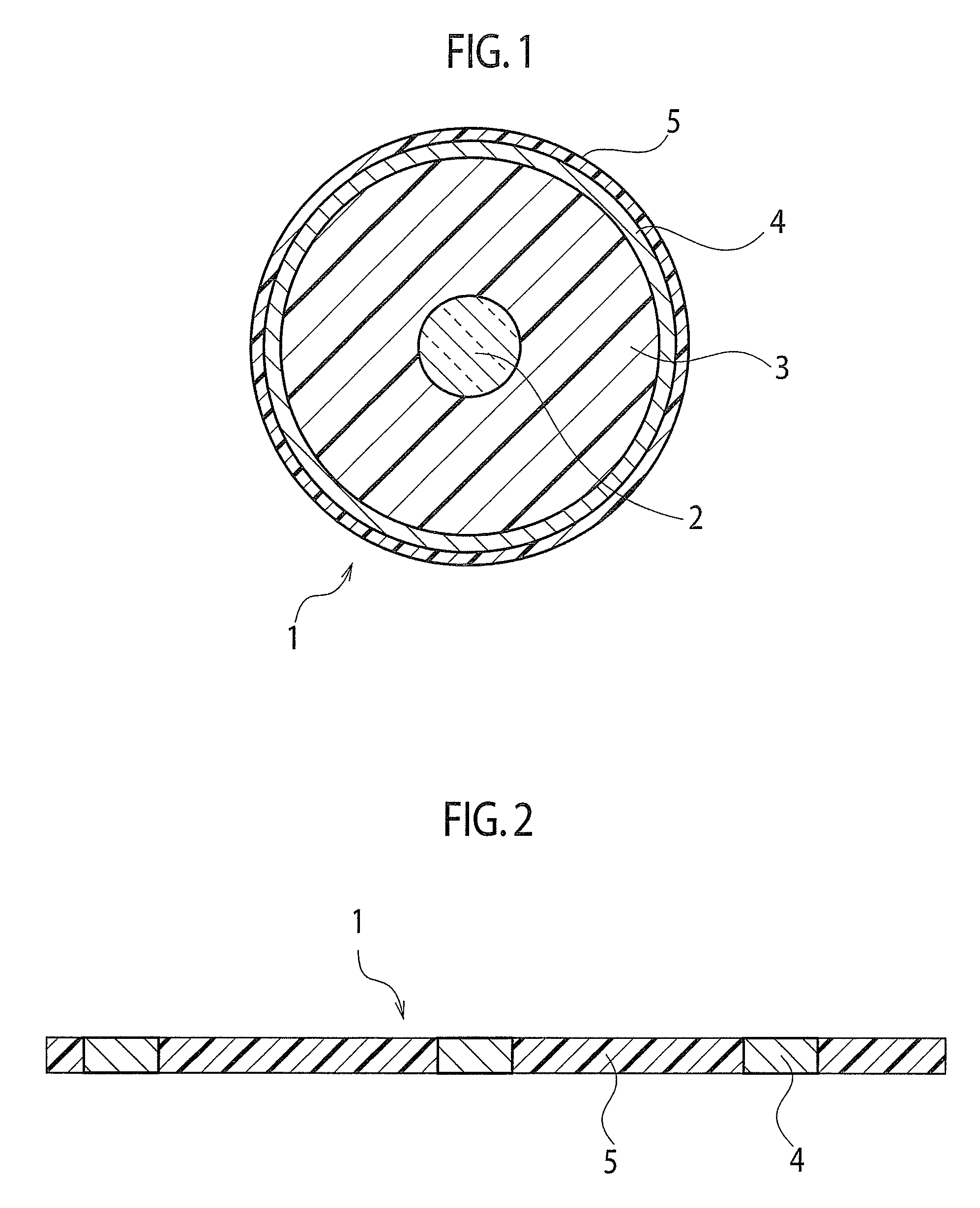
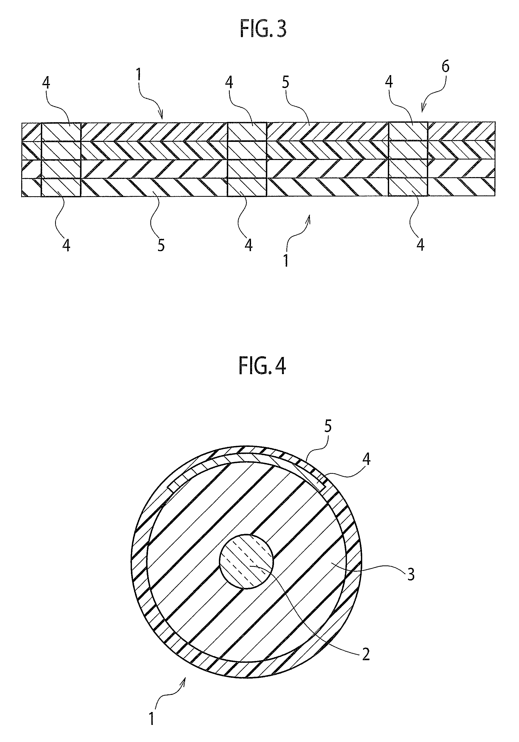
[0043]As Examples of the optical fiber ribbon according to the embodiment, optical fiber ribbons were formed of the optical fibers 1 with an outer diameter of the fiber coating 3 of 250 microns. The markings 4 had a mark length of 2 mm and a mark pitch of 50 mm and were provided intermittently in the longitudinal direction. The markings 4 were coated with the color layers 5. Four optical fibers 1 were arranged side by side so that the longitudinal positions of the same markings 4 of all the optical fibers 1 correspond to each other.

[0044]The material of the tape material 6 is an ultraviolet curing resin. The optical fibers 1 were coated with the tape material 6 into a tape.

[0045]FIG. 7 is plan views showing configurations of Comparative Examples of the optical fiber ribbon.

[0046]As Comparative Examples, the same optical fibers as those...


PUM


Abstract

An optical fiber ribbon includes: a plurality of optical fibers arranged in parallel; and a tape material covering the plurality of optical fibers into a tape, in which the plurality of optical fibers are coated respectively with translucent color layers of different colors, and in at least two of the plurality of optical fibers, markings for identifying the optical fiber ribbon are provided at a same position in a longitudinal direction of the optical fiber ribbon.

Description

CROSS-REFERENCE[0001]This application is a Continuation of PCT Application No. PCT / JP2011 / 058618, filed on Apr. 5, 2011, and claims the priority of Japanese Patent Application No. 2010-086959, filed on Apr. 5, 2010, the content of both of which is incorporated herein by reference.BACKGROUND OF THE INVENTION[0002]1. Field of the Invention[0003]The present invention relates to an optical fiber ribbon including a plurality of optical fibers which are joined in parallel and relates to an optical fiber cable and a wire configuration which include the optical fiber ribbons.[0004]2. Description of the Related Art[0005]As described in Japanese Patent Application Laid-open Publication No. 2007-178883, a conventionally proposed optical fiber ribbon includes a plurality of optical fibers which are joined in parallel. In such an optical fiber ribbon, the plurality of optical fibers, which are arranged in parallel, are coated with a tape material (a coating material). Each optical fiber includes...

Claims


Application Information

Patent Timeline
Patent Type & Authority Patents(United States)
IPC IPC(8): G02B6/44G02B6/04
CPCG02B6/4482G02B6/4403G02B6/4411
Inventor MATSUZAWA, TAKASHITAKE, YUKIKOISAJI, MIZUKIOSATO, KENOKADA, NAOKI
Owner FUJIKURA LTD
Why Eureka
Try Eureka