
Electrical connector assembly

a technology of electrical connectors and assembly parts, applied in the direction of electrical apparatus, connection, coupling device connection, etc., can solve the problems of increasing process complexity and cost, affecting the yield of the whole electrical connector assembly, so as to achieve cost reduction, facilitate manufacturing, and simplify the effect of the process

Inactive Publication Date: 2015-04-14
CHANG NAI CHIEN
View PDF2 Cites 6 Cited by
  • Summary
  • Abstract
  • Description
  • Claims
  • Application Information

AI Technical Summary

Benefits of technology

[0017]One objective of the present invention is to provide an electrical connector assembly having advantages of easy manufacturing, none fixture, and cost down.
[0018]Another objective of the present invention is to provide an electrical connector assembly having a wide range of assembly flexibility, hard to fracture, and capable of decreasing electromagnetic interference simultaneously.
[0024]In comparison with the related art, the present invention has the following effects:
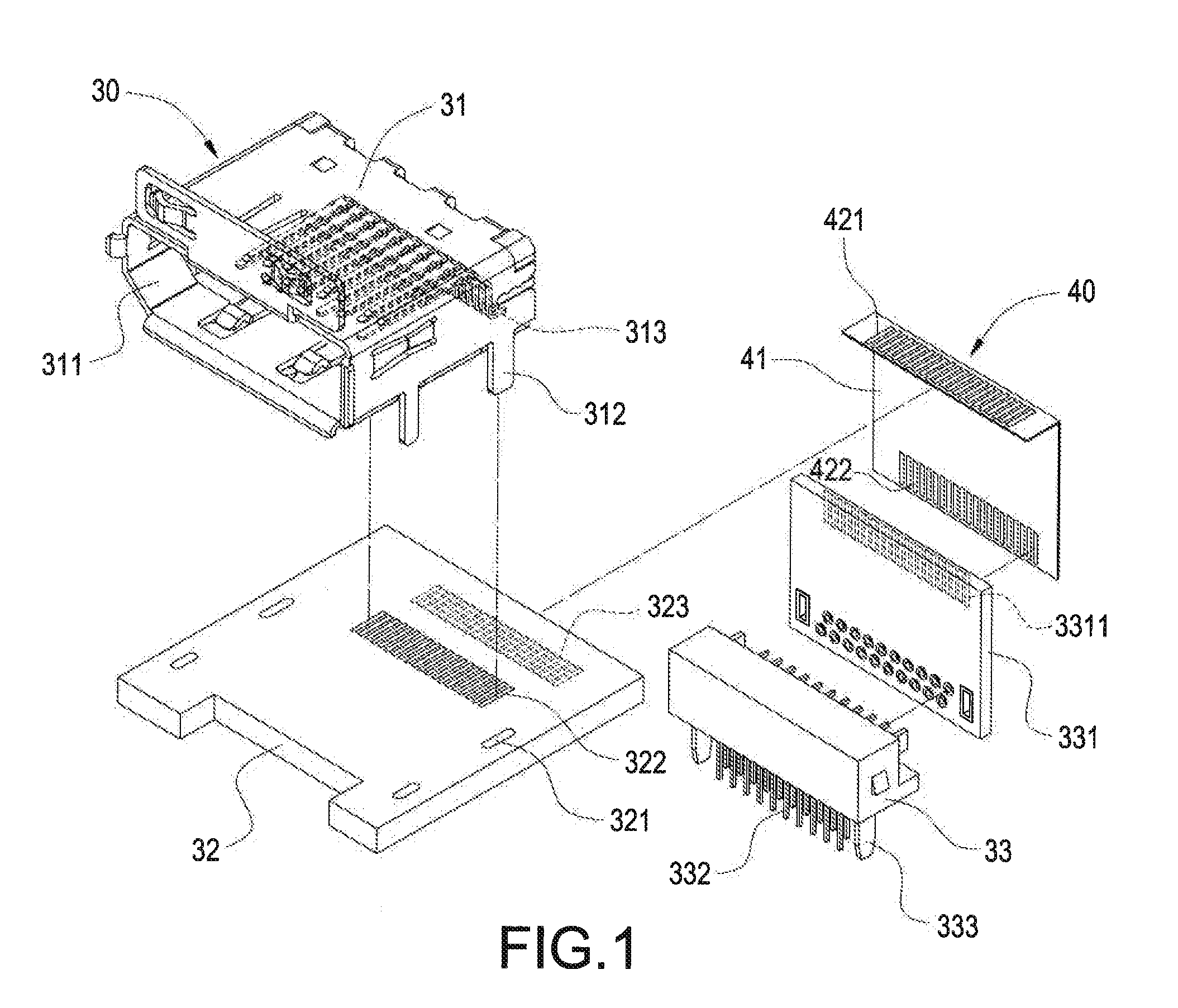
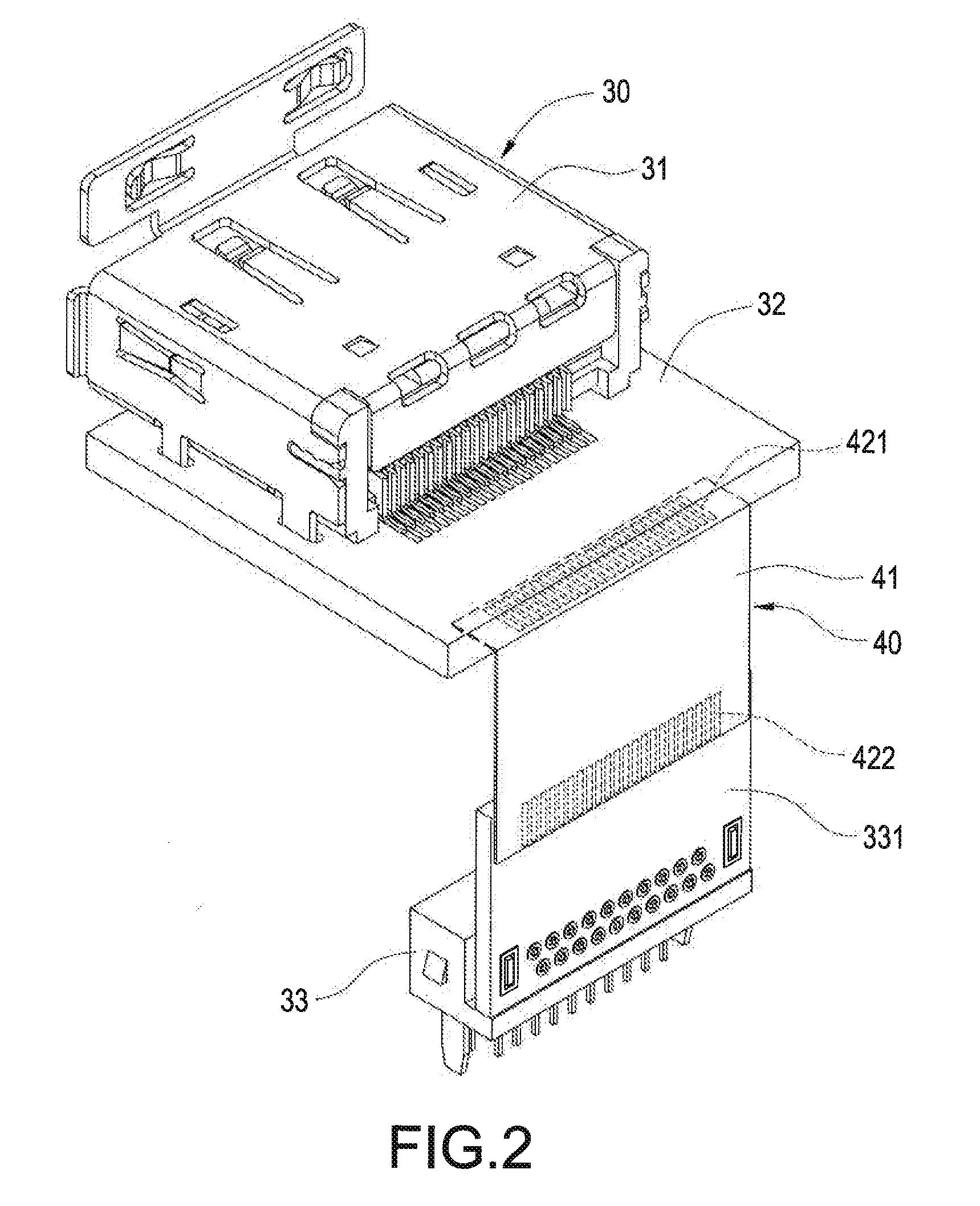
[0025]In the present invention, the electrical connector assembly has the second connector module located above the first connector module, and the second connector module is electrically connected to the external circuit board via the flexible conducting wire, so as to replace a traditional metal conducting pin. The flexible conducting wire can be a flexible flat cable (FFC) or a general electrical cable, such that when the second connector module is electrically connected. to the external circuit board, flexible conducting wires have different quantity of conductive terminals can be easily manufactured without any fixture. Accordingly, it can significantly achieve cost down and simplify process.
[0026]Further, flexibility of the flexible conducting wire can significantly decrease precision requirement between the second connector module and the external circuit board, so as to simplify assembly process and increase yield of the entire electrical connector assembly. In addition, the flexible conducting wire can absorb external impact or vibration, so as to decrease fracture probability of the conductive terminal.
[0027]Moreover, either of the flexible flat cable and the general electrical cable has an insulation cladding layer disposed on a surface thereof, such that the problem of electromagnetic interference can be solved at the same time. Hence, the present invention. can achieve a lot of functions, and thus has obviousness and usability.

Problems solved by technology

Since each kind of the electrical connector has the conducting pin with different quantity and length, a different fixture has to be designed, such that process complexity and cost may be increased.
Further, since the metal conducting pin does not have flexibility, precise alignment has to be made between the conducting pin and a socket of the external circuit board without errors.
Once the angle or location of the conducting pin is incorrect, the yield of the whole electrical connector assembly will be affected.
On other hand, since the traditional metal conducting pin lacks flexibility, once the electrical connector assembly is crashed or vibrated, the conducting pin could crack.
Moreover, the metal conducting pin may also be suffered to electromagnetic interference (EMI).

Method used


Image

  • Electrical connector assembly
  • Electrical connector assembly
  • Electrical connector assembly

Examples


Embodiment Construction

[0028]The detailed description and the technical content of the present invention are illustrated along with the accompanied drawings as follows. The accompanied drawings merely provide reference and description instead of a limit to the present invention.

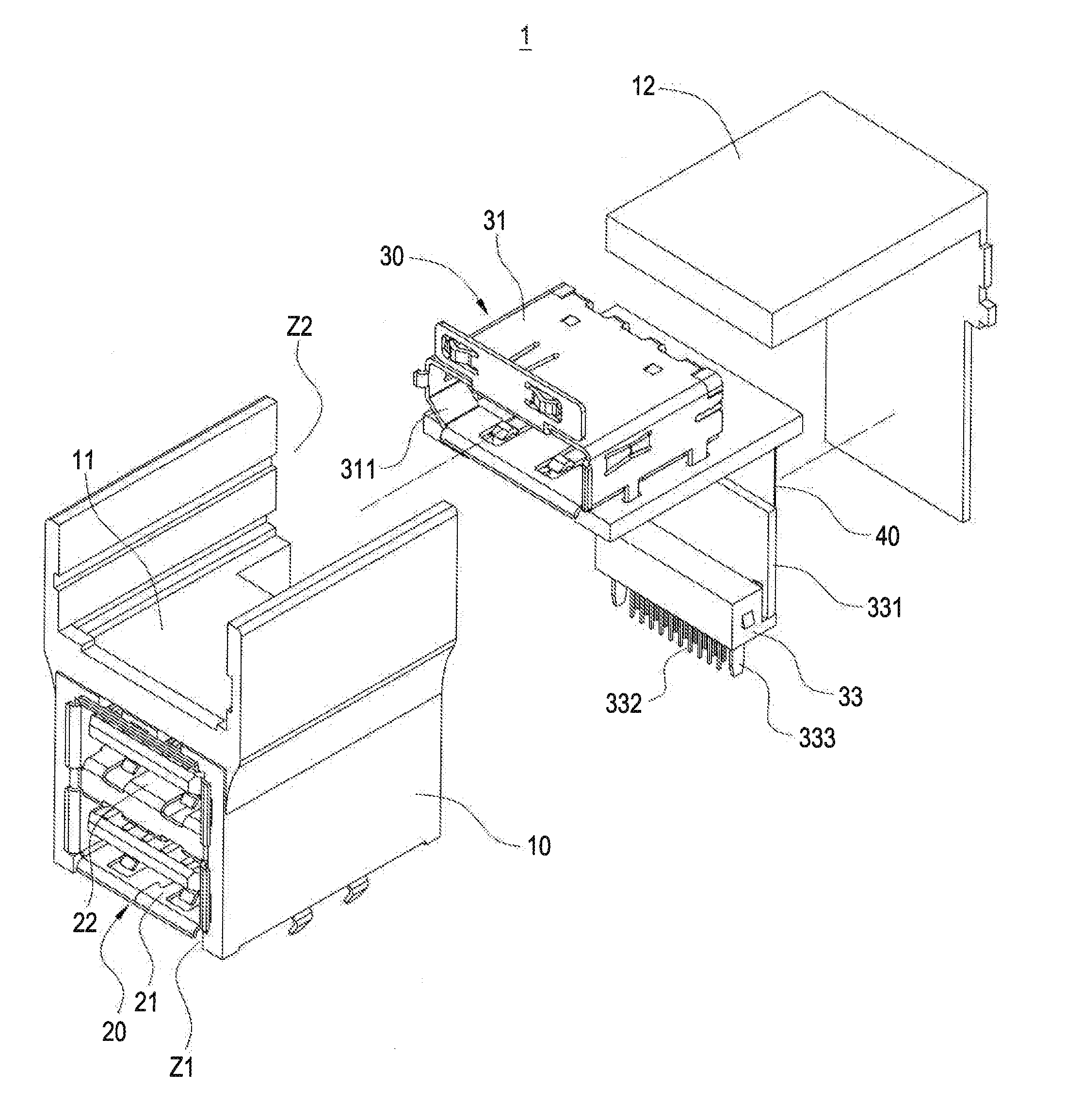
[0029]Please refer to FIG. 1 to FIG. 5, the present invention provides an electrical connector assembly 1 for electrically connecting an external circuit board (not shown). Persons skilled in the art can understand the external circuit board not illustrated in the drawings of the present invention.

[0030]In the present invention, the electrical connector assembly 1 comprises an insulating main body 10, a first connector module 20, at least one second connector module 30, and a flexible conducting wire 40.

[0031]As illustrated in FIG. 3, the insulating main body 10 is generally of H-shape and has a horizontal partition board 11. The insulating main body 10 has a first accommodation space Z1 located below the horizontal partition board...


PUM


Abstract

An electrical connector assembly for electrically connecting an external circuit board has an insulating main body, a first connector module, a second connector module and a flexible conducting wire. The first connector module is disposed inside the insulating main body and electrically connected to the external circuit board. The second connector module is disposed inside the insulating main body and located above the connector module. The flexible conducting wire has two ends electrically connected to the second connector module and the external circuit board. The flexible conducting wire replaces a traditional metal conducting pin, so as to achieve simple process and decrease electromagnetic interference.

Description

BACKGROUND OF THE INVENTION[0001]1. Field of the Invention[0002]The present invention relates to an electrical connector assembly, in particular, to an electrical connector assembly having a flexible conducting wire.[0003]2. Description of Related Art[0004]Followed by rapid technology development, various kinds of electrical connector assemblies have been invented for electrical connection between electronic components and circuit boards. In order to decrease an occupied bottom surface of an electrical connector assembly and to increase the quantity of an electrical connector, the industry vents a stacked electrical connector assembly having a plurality of vertically stacked electrical connectors.[0005]According to the present technique level, the stacked electrical connector assembly has a lower electrical connector. The lower electrical connector has conducting pins capable of electrically inserting downward into an external circuit board in a very short distance. In the contrast,...

Claims


Application Information

Patent Timeline
Patent Type & Authority Patents(United States)
IPC IPC(8): H01R13/60H01R12/50H01R12/71H01R12/73
CPCH01R12/50H01R12/716H01R12/737H01R27/02
Inventor CHANG, NAI-CHIEN
Owner CHANG NAI CHIEN
Learn More