
Image quality by printing frequency adjustment using belt surface velocity measurement

a belt surface velocity and printing frequency technology, applied in printing, other printing apparatus, etc., can solve problems such as color registration errors, image quality defects, and print image defects, and achieve the effect of improving image quality

Active Publication Date: 2015-04-14
XEROX CORP
View PDF9 Cites 28 Cited by
  • Summary
  • Abstract
  • Description
  • Claims
  • Application Information

AI Technical Summary

Benefits of technology

This approach significantly improves image quality by achieving color-to-color registration accuracy within 10-20 microns, reducing positional errors and enhancing the overall image quality compared to conventional systems.

Problems solved by technology

Deviations of belt surface velocity from a nominal value cause defects in the printed image.
Deviations in the belt transport velocity can cause color registration error, i.e., color separations so that colors are not printed at the intended locations.
This results in image quality defects.
In a belt module, the angular velocity of a roll is not an extremely accurate measure of the belt surface or media transport velocity.
Color-to-color registration errors are positional errors, i.e. they result from the integral of velocity errors over time.
For long wave lengths, small velocity errors can integrate to substantial position errors.
The belt length represents a long wave length and belt thickness variations are known to cause substantial color-to-color registrations errors.

Method used


Image

  • Image quality by printing frequency adjustment using belt surface velocity measurement
  • Image quality by printing frequency adjustment using belt surface velocity measurement
  • Image quality by printing frequency adjustment using belt surface velocity measurement

Examples


example 1

[0035]Data were collected using a belt surface roll-mounted encoder, which has a tracking wheel mounted to the end of a rotatable shaft. The tracking wheel is loaded directly against the belt and measures the velocity of the belt when it moves.

[0036]Although the printing frequency is proportional to belt surface velocity, the validation data is represented in terms of positional information, which represents color-to-color registration errors. It also more clearly demonstrates the contribution of longer wave length, smaller errors. The positions were calculated as the integral over time of the measured velocity minus its average velocity over a certain time interval (about 58 seconds). The results are shown in FIG. 6.

[0037]The surface encoder position A shows the contributions from all error sources, including roll / wheel errors, belt thickness variations and belt drive servo errors. Roll / wheel errors are typically due to eccentricity of roll / wheels, mounting error, etc. These types ...

example 2

[0040]Estimates to determine the approximate color-to-color registration errors using different design, measurement and compensation approaches (based on estimated magnitudes of error sources) were generated based on historical test results. Some of the estimates assumed synchronous design rules, wherein the circumference of the drive roll is an integer multiple of the spacing (S) (see FIG. 3.) between adjacent print heads. This can require a larger printing system and result in less efficient space utilization (i.e., size of the system). The following six different printing systems were estimated to determine the approximate registration error in microns.

[0041]1. Constant velocity transport using non-synchronous design rules.

[0042]2. Constant velocity transport using synchronous design rules.

[0043]3. Reflex printing based on drive roll encoder using non-synchronous design rules.

[0044]4. Reflex printing based on drive roll encoder using synchronous design rules.

[0045]5. Reflex print...


PUM


Abstract

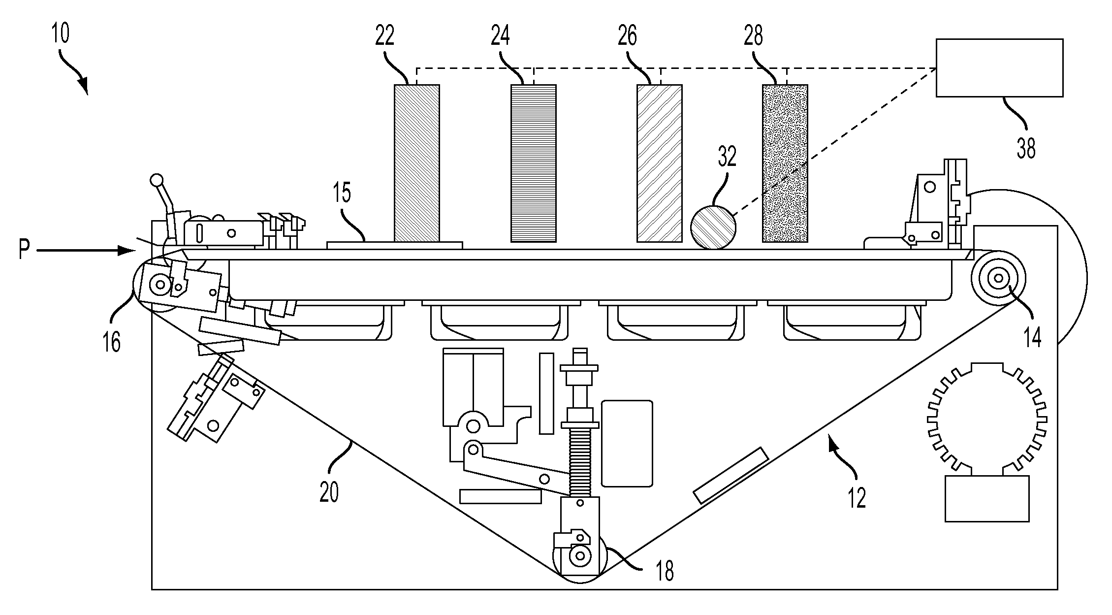
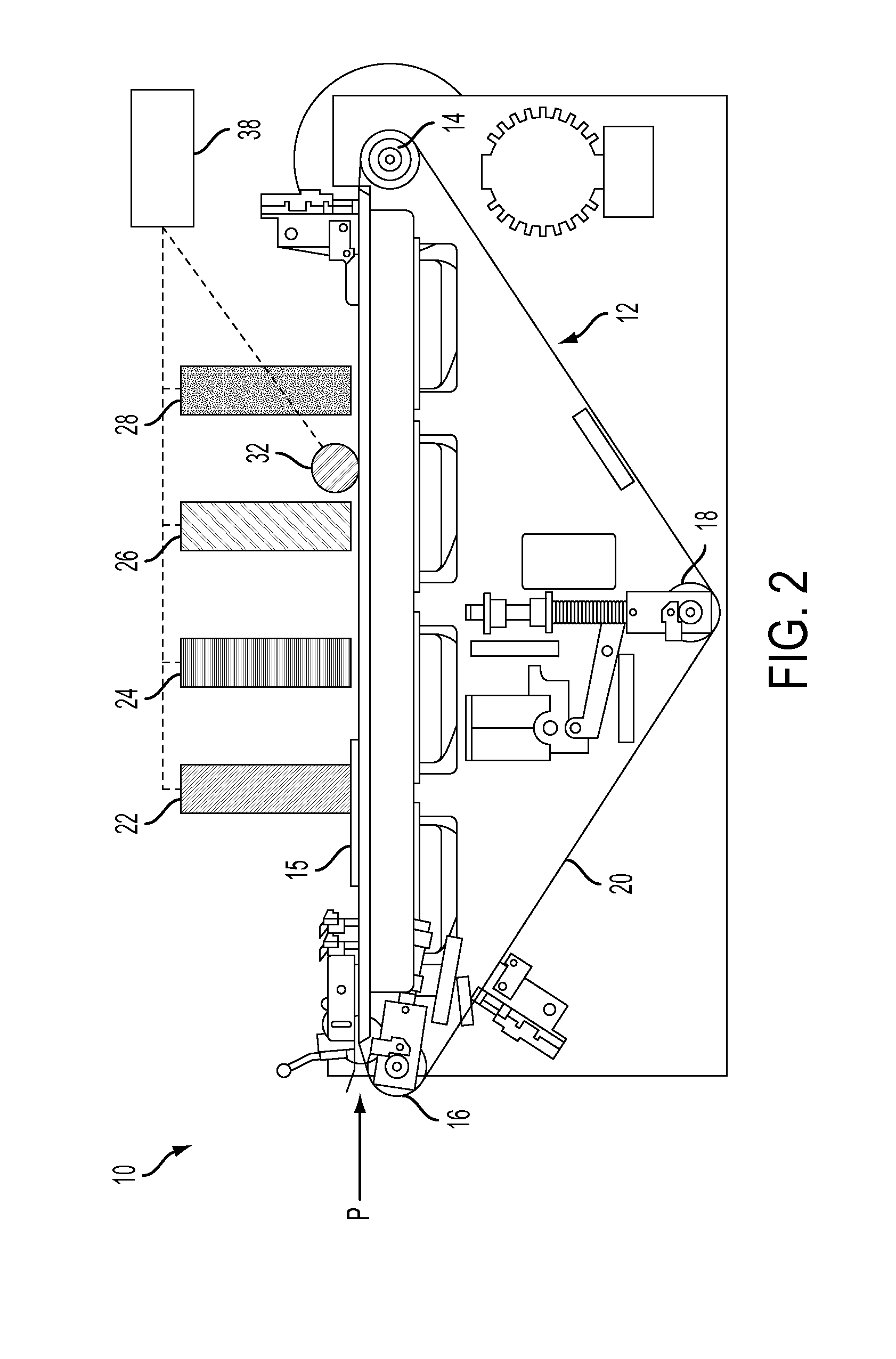
Embodiments described herein are directed to a reflex printing system with improved image quality. A media transport moves a media substrate or an intermediate belt along a media path in a process direction past the two or more print heads, which deposit inks onto the media substrate or the intermediate belt. A velocity measuring device directly measures and transmits the speed of the surface of belt or media that is to receive the image to a controller, which sends print commands to the two or more print heads to control the frequency of the printing. The inks deposited on the media substrate or intermediate belt have a color registration of from 10 to 20 microns.

Description

BACKGROUND[0001]1. Technical Field[0002]The presently disclosed technologies are directed to a system and method for improving image quality by adjusting the printing frequency. The system and method described herein measure the belt surface velocity and use it to adjust the printing frequency.[0003]2. Brief Discussion of Related Art[0004]In order to ensure good image quality (IQ) in cut sheet direct to paper (DTP) ink jet printing, a media transport system must transport the media through the print zone at a controlled rate. Methods of choice for the media transport use a belt module that tacks the media to the surface of the belt using vacuum or electrostatic forces. In order to assure accurate printing, the belt with the tacked media must be held firmly against a support. Deviations of belt surface velocity from a nominal value cause defects in the printed image. These deviations can be caused by, but are not limited to, velocity variations caused by belt thickness variations, va...

Claims


Application Information

Patent Timeline
Patent Type & Authority Patents(United States)
IPC IPC(8): B41J29/38B41J29/393B41J2/045B41J11/00
CPCB41J11/007B41J2/04503B41J2/04581B41J2002/012B41J11/44B41J29/393
Inventor DE JONG, JOANNES N. M.MANDEL, BARRY P.
Owner XEROX CORP
Learn More