
Customization of manufactured products

Active Publication Date: 2015-03-31
W A KRAPF
View PDF8 Cites 5 Cited by
  • Summary
  • Abstract
  • Description
  • Claims
  • Application Information

AI Technical Summary

Benefits of technology

The invention is a system, device, and method that allows a person to create custom design information for an object before it is made. This is done through a user interface that can be transmitted to a manufacturer. The design information includes a visual representation of the object, which can be created by arranging text and graphics based on a grid pattern. The grid pattern has rows and columns with independent and variable dimensions, and can be arranged in a hierarchical manner. The technical effect of this invention is that it allows for greater customization and flexibility in designing objects, resulting in improved efficiency and accuracy in manufacturing.

Problems solved by technology

In some circumstances, the iterative process is time consuming and inefficient and manufacture of the customized product can result in a less than satisfactory result due to lack of complete communication between a person, and the manufacturer receiving, the customized design.

Method used


Image

  • Customization of manufactured products
  • Customization of manufactured products
  • Customization of manufactured products

Examples


Embodiment Construction

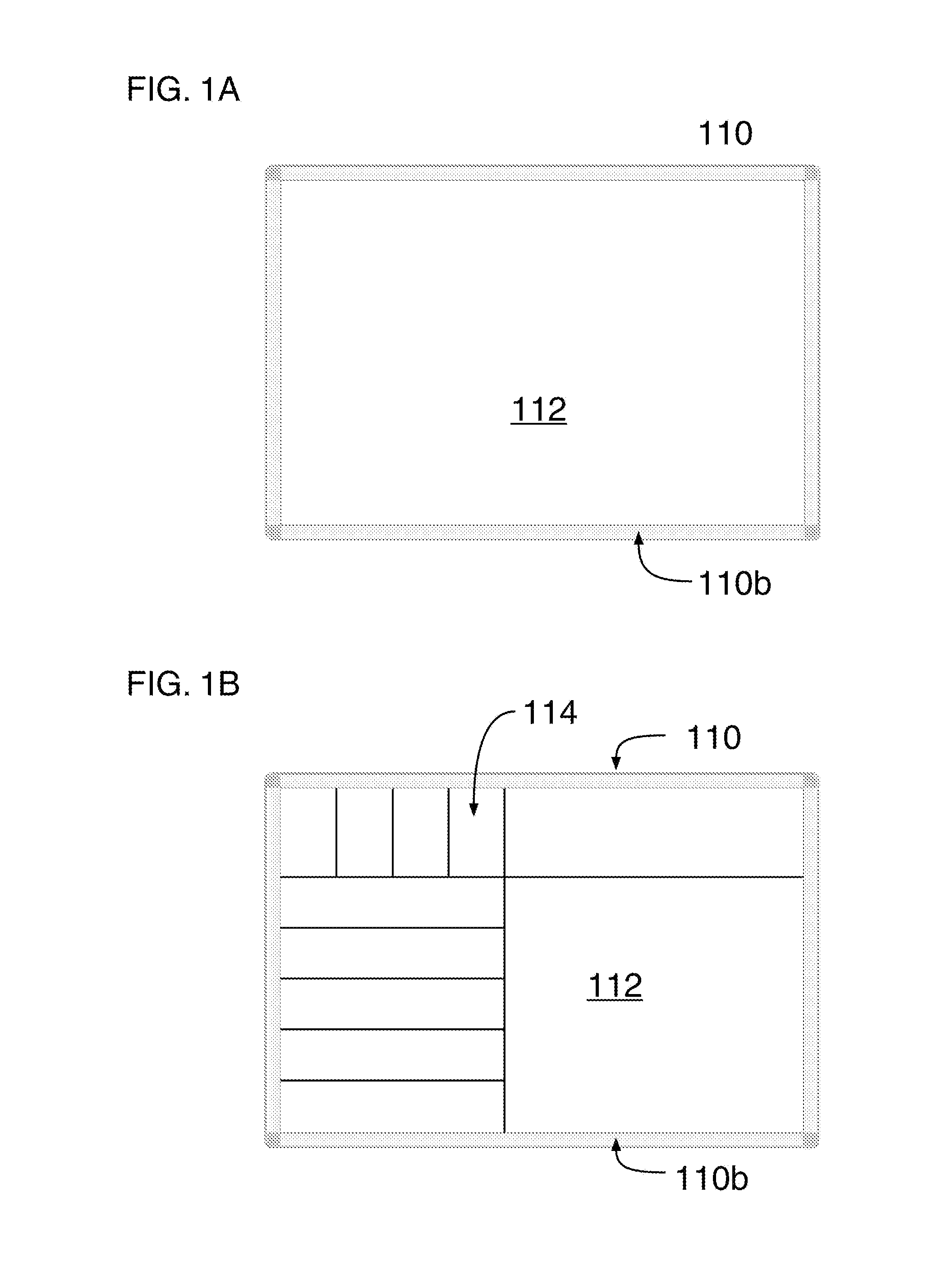
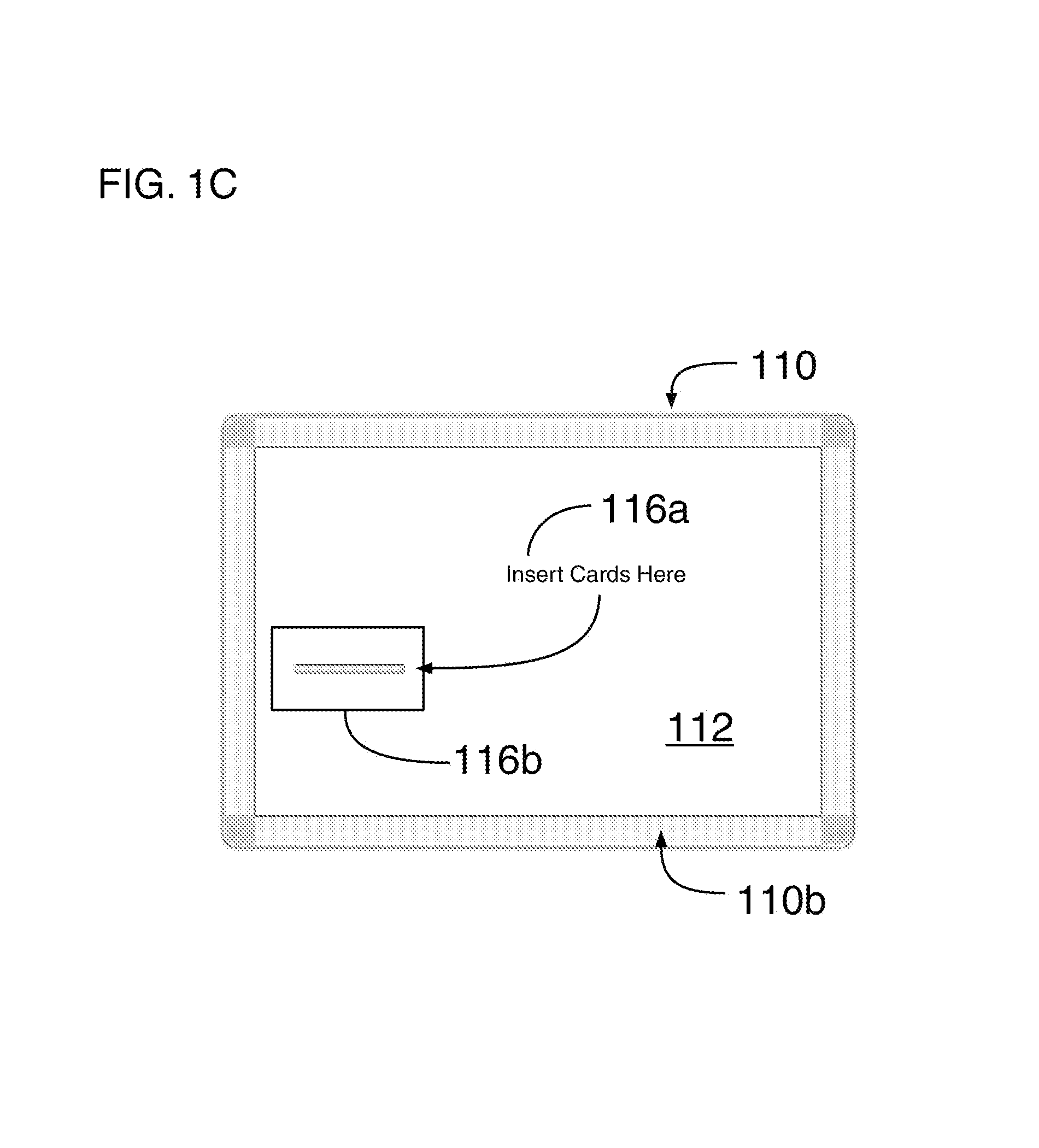
[0019]FIG. 1A illustrates a frontal view of an exemplary first embodiment of a display board 110. The type of display board shown is referred to as a dry erase display board 110 or “white board”110. The display board 110 is defined by a board element consisting of a front panel that is retained along each of its lateral edges within a display / drawing area portion 112 and a frame portion 110b. In this embodiment, the display / drawing area 112 is also referred to herein as a drawing surface 112, a display surface 112, a drawing area 112 or a display area 112. The display / drawing area 112 is surrounded by a frame 110b along each of its lateral edges thereof defining its outer perimeter.

[0020]The display area 112 is a planar surface that is constructed from a metal alloy, such as steel that is coated with a substance, typically of a shade of white color, that can be further and permanently coated with other substances of various colors and patterns (not shown) during its manufacture. Aft...


PUM


Abstract

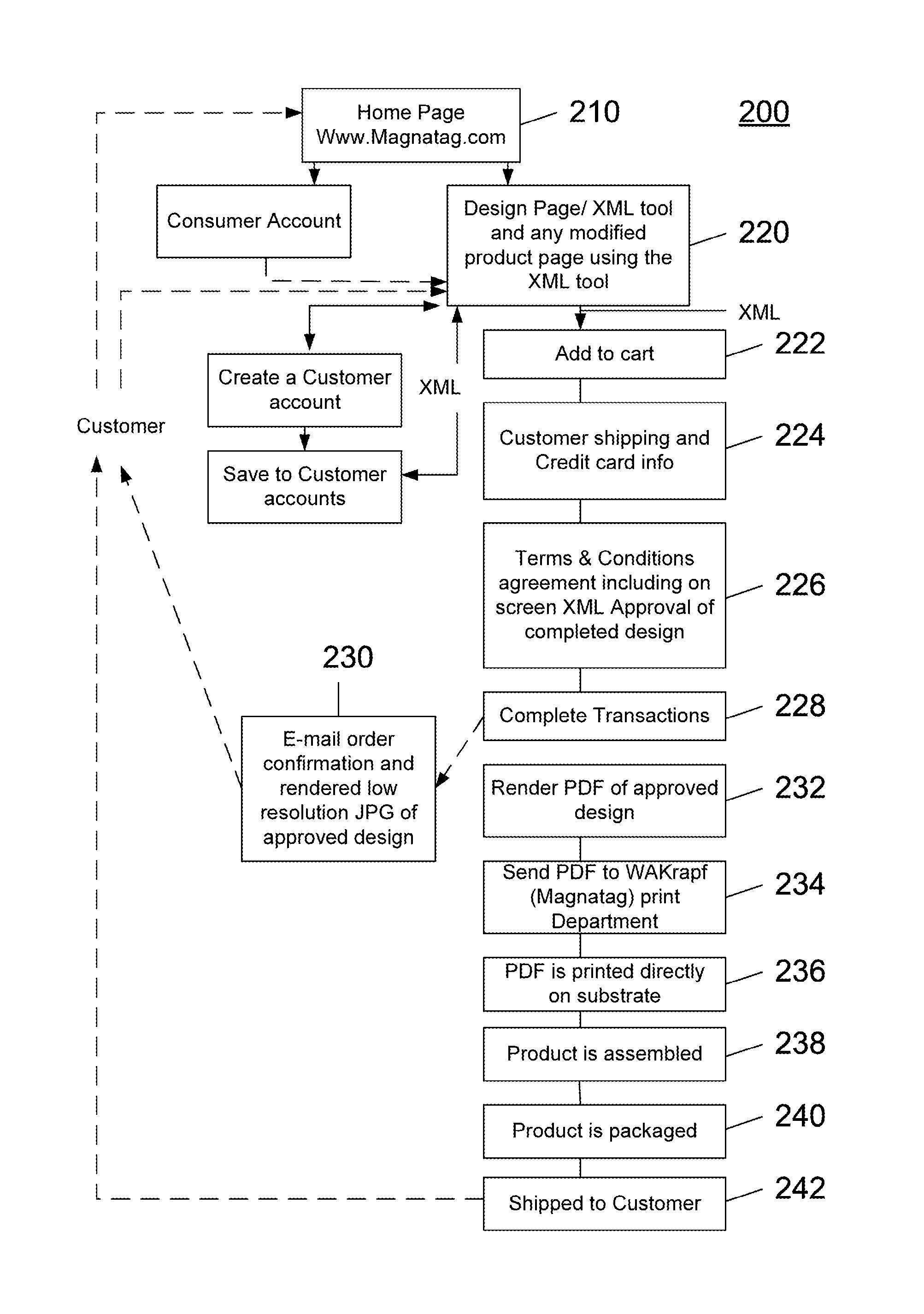
A system, apparatus and method for a person to communicate customized design information for an object, such as a product at a time prior to its manufacture. A network accessible communications channel and user interface is provided that enables the person to communicate design information, including a visual representation of the product, prior to its manufacture.

Description

CROSS REFERENCE TO RELATED PATENT APPLICATIONS[0001]This is a non-provisional patent application that claims priority and benefit to U.S. provisional patent application Ser. No. 61 / 388,241 that was filed on Sep. 30, 2010 and entitled “Design Customization of Manufactured Products”, the aforementioned (61 / 388,241) patent application is incorporated herein by reference in its entirety.FIELD OF THE INVENTION[0002]This invention generally relates to a system, apparatus and method for a person to communicate custom design information associated with an object, such as a product to be manufactured. A user interface, and optionally a communications channel, is provided that enables the person to communicate the customized design information, including a visual representation associated with the object, prior to its manufacture.COMPUTER PROGRAM LISTING APPENDIX[0003]Enclosed with the specification are two (2) compact discs (Copy 1 and Copy 2) which are identical. The files recorded on each ...

Claims


Application Information

Patent Timeline
IPC IPC(8): G06F19/00
CPCG06Q30/0621G06F30/00
Inventor AMBROSE, DENNIS W.KRAPF, CHRISTIAN Q.
Owner W A KRAPF
Learn More