
Solar tracker for photovoltaic power generation

a solar tracker and power generation technology, applied in the safety of solar heat collectors, pv power plants, lighting and heating apparatus, etc., can solve the problems of increasing manufacturing and construction costs, affecting the operation of the device, and the frequent out-of-order of the tracking device, so as to reduce the operating and management costs of the device, reduce the diurnal change, and reduce the consumption of firm power of the driving unit for tracking the sun.

Inactive Publication Date: 2015-03-31
HYPER
View PDF12 Cites 17 Cited by
  • Summary
  • Abstract
  • Description
  • Claims
  • Application Information

AI Technical Summary

Benefits of technology

[0009]An embodiment of the present invention is related to providing of a solar tracker including a driving device which has a simple structure with rigidity and endurance to sufficiently endure against wind pressure, and can accurately control an altitude angle and an azimuth angle through a simple mechanical operation.
[0012]Since the locking type crisscross connectors are vulnerable to breakdown due to an external effort force acting on the side surfaces thereof in the case where they are used on the structure, rotation locking portions for restricting rotational movement with two degrees of freedom are provided to restrict relative movement of the locking type crisscross connectors that are connected to the altitude angle adjustment direct cylinder and the azimuth angle adjustment direct cylinder after the altitude angle adjustment direct cylinder and the azimuth angle adjustment direct cylinder complete the angle adjustment operations so that the overall structure can be structurally stabilized as a rigid body.
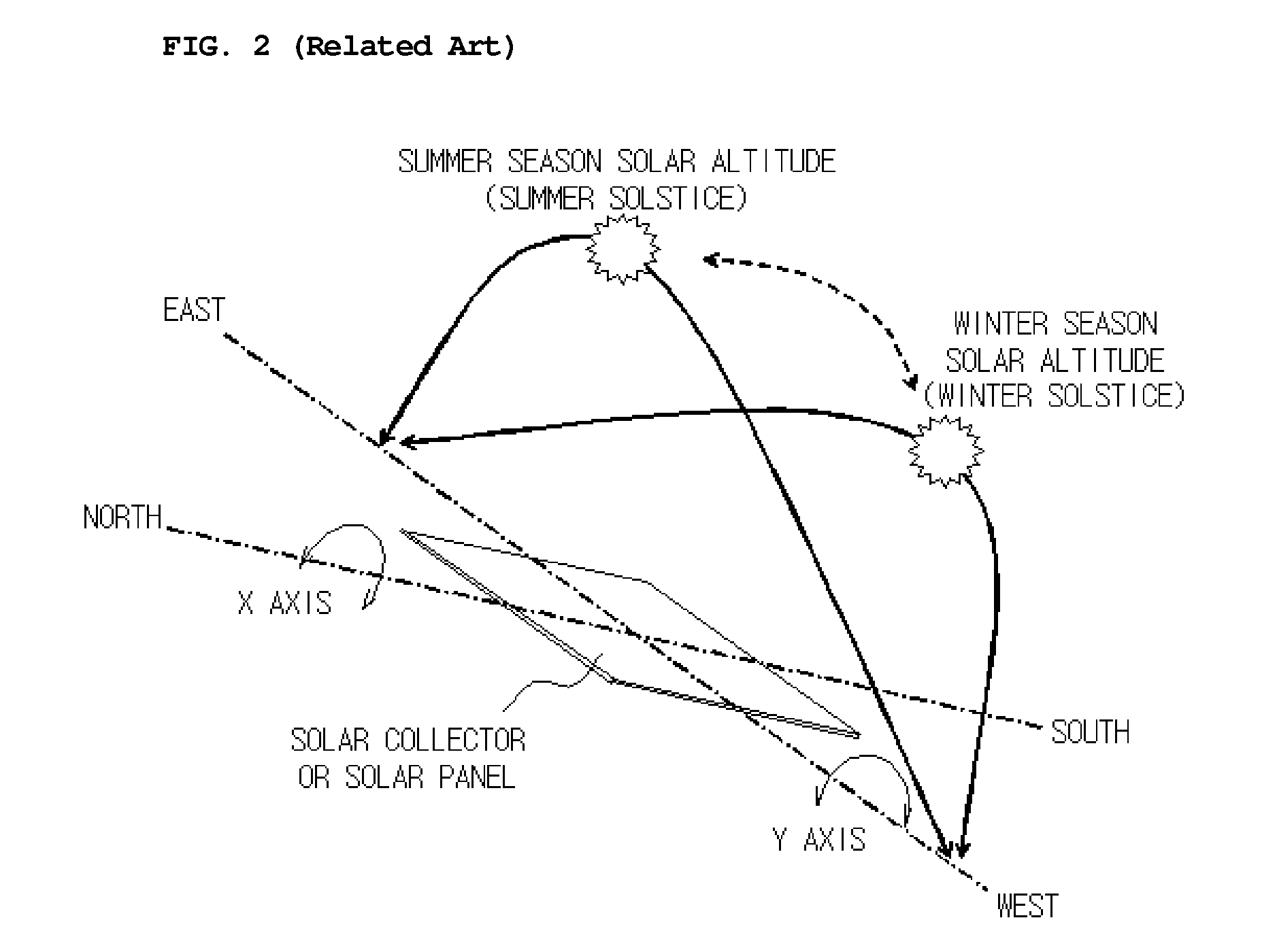
[0015]As illustrated in FIG. 2, the altitude angle of the sun, which is repeatedly changed according to seasons of the year in the range of the winter solstice having the lowest altitude angle and the summer solstice having the highest altitude angle, has an extremely small diurnal change, whereas the azimuth angle of the sun is repeatedly changed in one direction, that is, from sunup to sundown, in a day. The solar tracker according to the present invention fixes the altitude angle until the altitude of the sun secedes from a predetermined range after matching the altitude through once driving of one shaft that tracks the altitude angle, and drives only the other shaft that tracks the east-west azimuth angle in daily repetition. Accordingly, the consumption of firm power of the driving unit for tracking the sun can be minimized, and the operating and management costs of the device can be reduced.
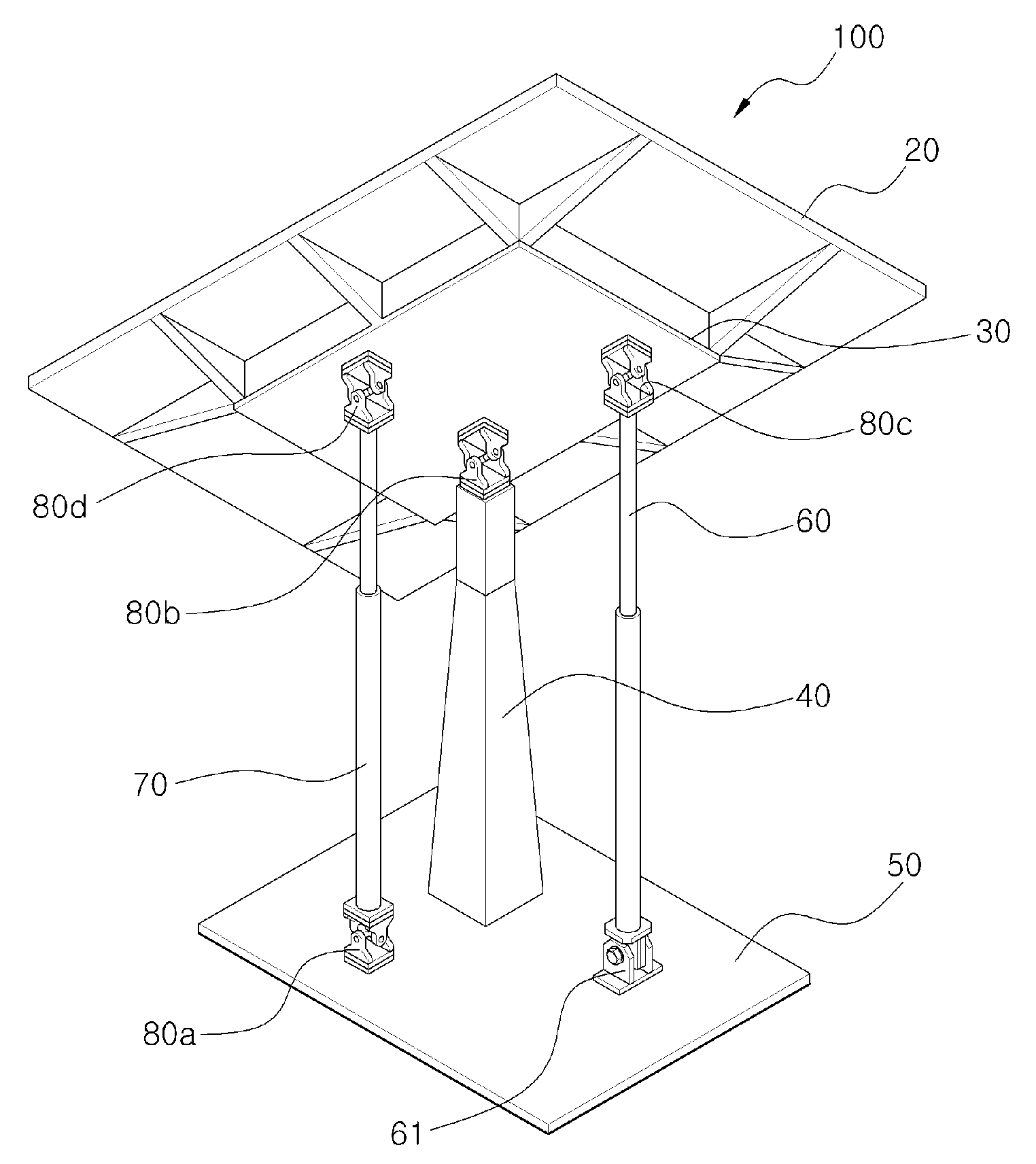
[0016]According to the solar tracker according to the present invention, since the direct cylinder that is a driving device for adjusting the angle of the solar cell plate also serves as the base structure of the device, the structure of the driving device can be remarkably simplified to unlimitedly lengthen the size and capacity of the photovoltaic power generator per unit device, the manufacturing and constructing costs can be greatly reduced, and the endurance can be heightened.
[0017]Since the solar tracker according to the present invention can open and close the plurality of solar cell panels, the wind pressure that acts on the while solar cell plate is mitigated by opening a part of or all the solar cell panels when the wind pressure reaches the predetermined strength, and thus the safety and the endurance of the overall structure of the solar tracker can be secured.
[0018]Further, according to the solar tracker according to the present invention that uses the locking type crisscross connectors and the direct cylinders, the weight of the large-capacity structure and the external effort force such as wind pressure can be appropriately dispersed to and supported by the main post and the direct cylinders, and the solar tracker can be installed with a high height from the ground. Accordingly, the utilization of the space below the solar tracker becomes natural and the damage of the green space can be minimized.

Problems solved by technology

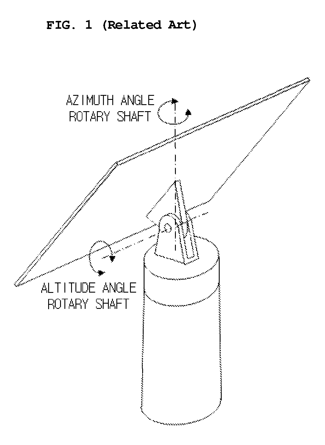
Accordingly, the solar tracker in the related art has the problems that complicated mathematical calculations through a computer are required, or precise control and frequent driving of the tracking devices are required to cause the tracking devices to frequently get out of order.
Accordingly, the structure becomes complicated with heavy weight, and the manufacturing and constructing costs are increased.

Method used


Image

  • Solar tracker for photovoltaic power generation
  • Solar tracker for photovoltaic power generation
  • Solar tracker for photovoltaic power generation

Examples


Embodiment Construction

[0040]Hereinafter, a solar tracker according to preferred embodiments of the present invention will be described in detail with reference to the accompanying drawings.

[0041]FIG. 3 is a perspective view of a solar tracker for photovoltaic power generation according to an embodiment of the present invention.

[0042]As illustrated in FIG. 3, a solar tracker 100 that is driven to trace solar light depending on the change of solar altitude and azimuth includes a solar cell plate 20 including one or more solar cell panels 10, an upper structure 30 on which the solar cell plate 20 is mounted, and a main post 40 and a base bottom portion 50 supporting the load of the solar tracker 100 for supporting the upper structure 30.

[0043]At this time, it is preferable that the base bottom portion 50 may be formed of a concrete or steel structure to sufficiently endure the turnover or tilting of the solar tracker 100 or strong wind pressure.

[0044]Further, the solar tracker includes an altitude angle adj...


PUM


Abstract

A solar tracker is provided to fix an altitude angle until the altitude of the sun secedes from a predetermined range after matching the altitude through once driving of one shaft that tracks the altitude angle and to drive only the other shaft that tracks an east-west azimuth angle in daily repetition in a state where the altitude angle of the sun, which is repeatedly changed according to seasons of the year in the range of the winter solstice having the lowest altitude angle and the summer solstice having the highest altitude angle, has an extremely small diurnal change, whereas the azimuth angle of the sun is repeatedly changed in one direction, that is, from sunup to sundown, in a day. Accordingly, consumption of firm power of a driving unit for tracking the sun can be minimized, and the operating and management costs of the device can be reduced.

Description

CROSS-REFERENCE TO RELATED APPLICATION[0001]This application is based on and claims priority from Korean Patent Application No. 10-2012-0101422, filed on Sep. 13, 2012 in the Korean Intellectual Property Office, the disclosure of which is incorporated herein in its entirety by reference.BACKGROUND OF THE INVENTION[0002]1. Field of the Invention[0003]The present invention relates to a solar tracker for photovoltaic power generation. More particularly, the present invention relates to a solar tracker for photovoltaic power generation, which tracks an orientation movement of the sun in a day and a change of solar altitude that is the height of the sun depending on seasons using a direct cylinder to heighten power generation efficiency through forming of a solar cell plate at right angles to the sun to correspond to the movement (trace) of the sun.[0004]2. Description of the Prior Art[0005]In order to make a solar cell plate positioned at right angles to the sun, a solar tracker must dr...

Claims


Application Information

Patent Timeline
Patent Type & Authority Patents(United States)
IPC IPC(8): F24J2/46F24J2/54H02S20/32F24S50/20
CPCF24J2/5431F24J2/4638Y02E10/47F24S30/455F24S2030/13F24S30/45F24S40/85F24S30/48Y02E10/50H02S20/32
Inventor EOM, BOON-DO
Owner HYPER
Learn More