
Shielded connector

a shield case and connector technology, applied in vehicle connectors, substation/switching arrangement details, coupling device connections, etc., can solve the problem of product development and labor intensiveness, and achieve the effect of not reducing the sealing performance of the part attached to the shield cas

Active Publication Date: 2015-03-31
YAZAKI CORP
View PDF22 Cites 51 Cited by
  • Summary
  • Abstract
  • Description
  • Claims
  • Application Information

AI Technical Summary

Benefits of technology

The present invention solves the problem of decreased sealing performance when external cables are repeatedly attached and detached from a shield case. This is achieved through a design that ensures the sealing performance of the attached part of the shield case is not compromised even after multiple attachment and detachment cycles. Additionally, the invention simplifies the construction of the device-side resin housing by eliminating the need for a separate hood part to accommodate the distal end of the cable-side connector. Furthermore, the invention improves the connecting strength in screw-connecting by ensuring an adequate length for the screw hole as the mating shell fixing part.

Problems solved by technology

Therefore, there is a problem that much labor is necessary for product development in response to the change of the dimension of the attached part of the shield case.

Method used


Image

  • Shielded connector
  • Shielded connector
  • Shielded connector

Examples


first embodiment

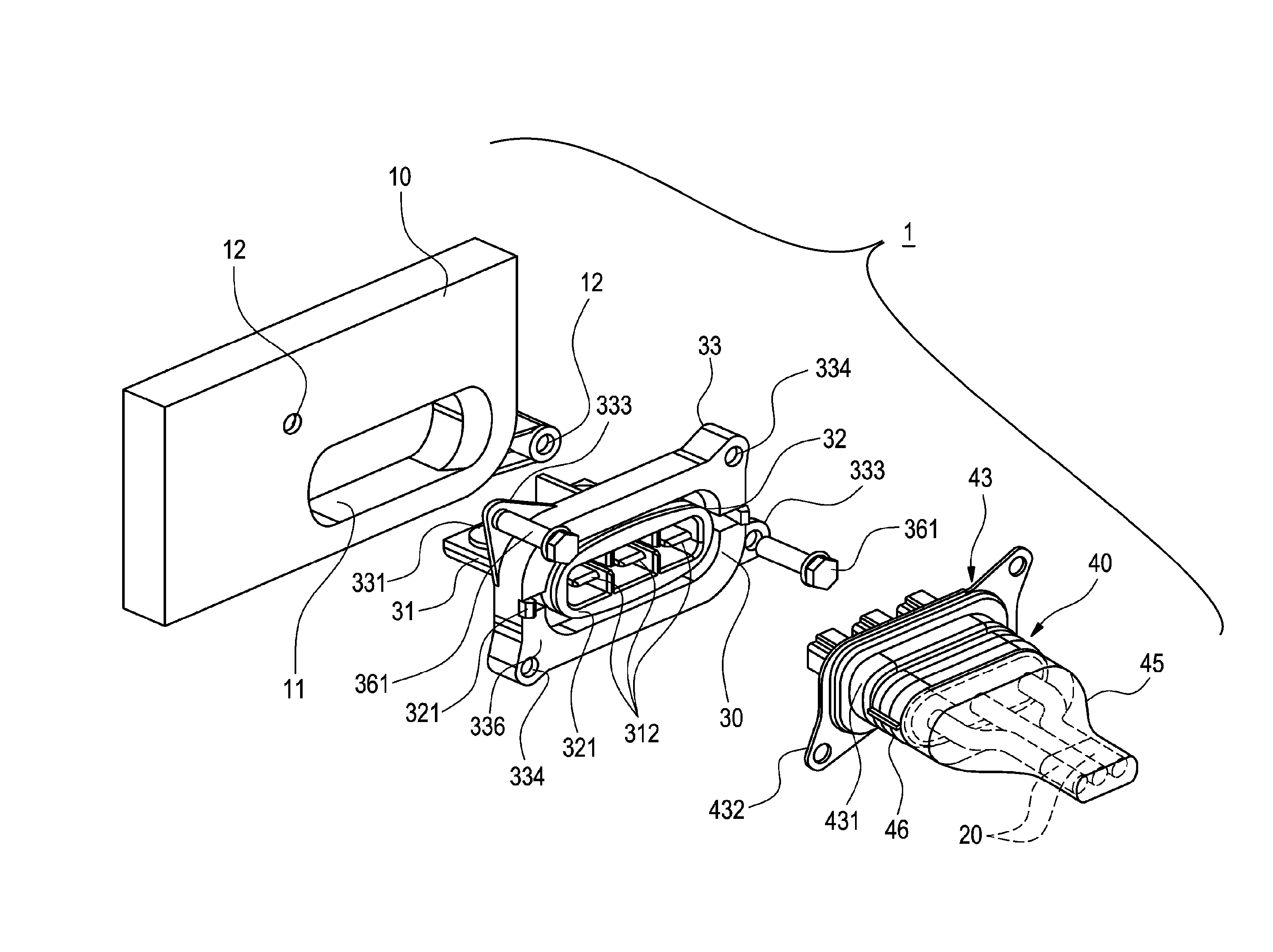
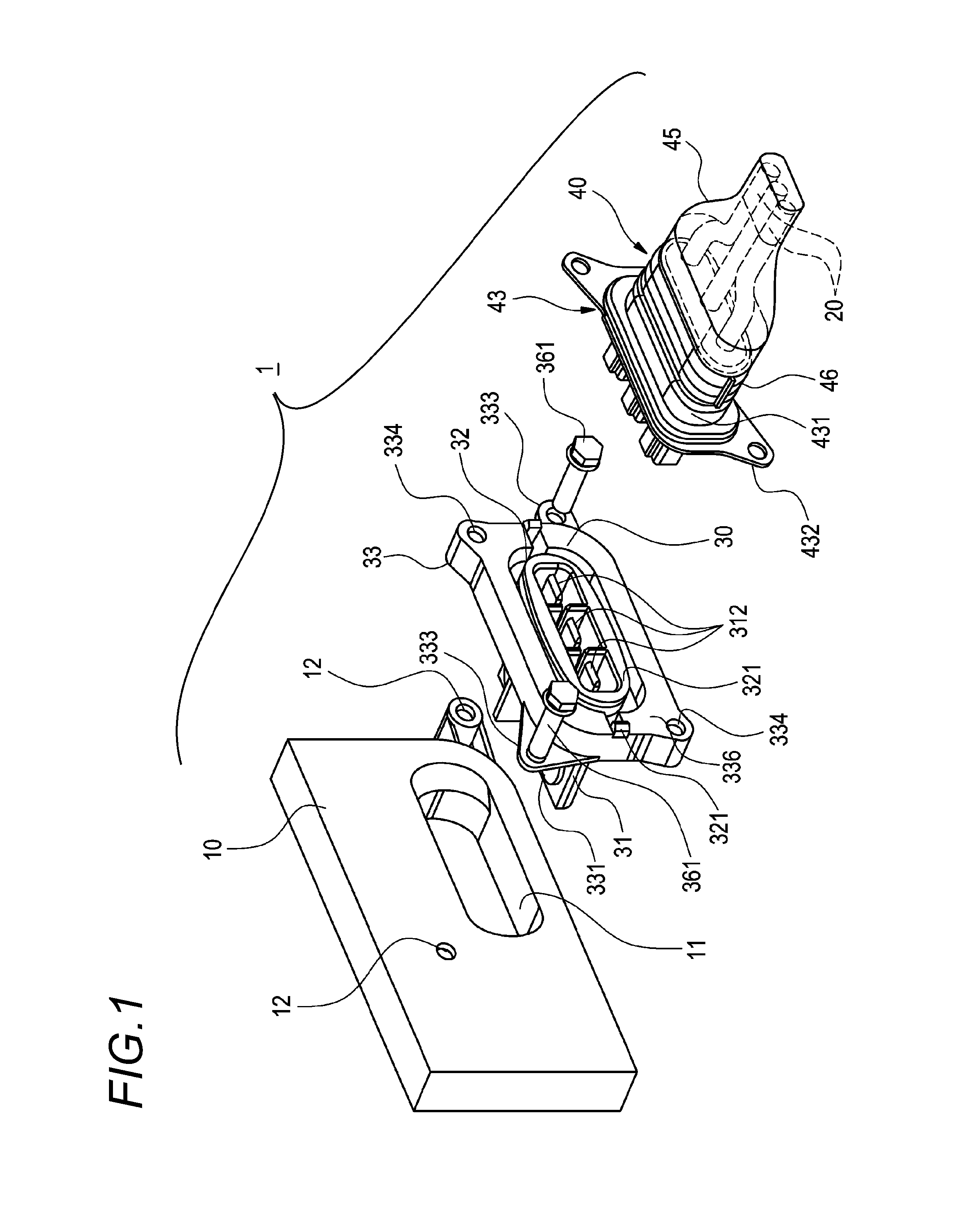
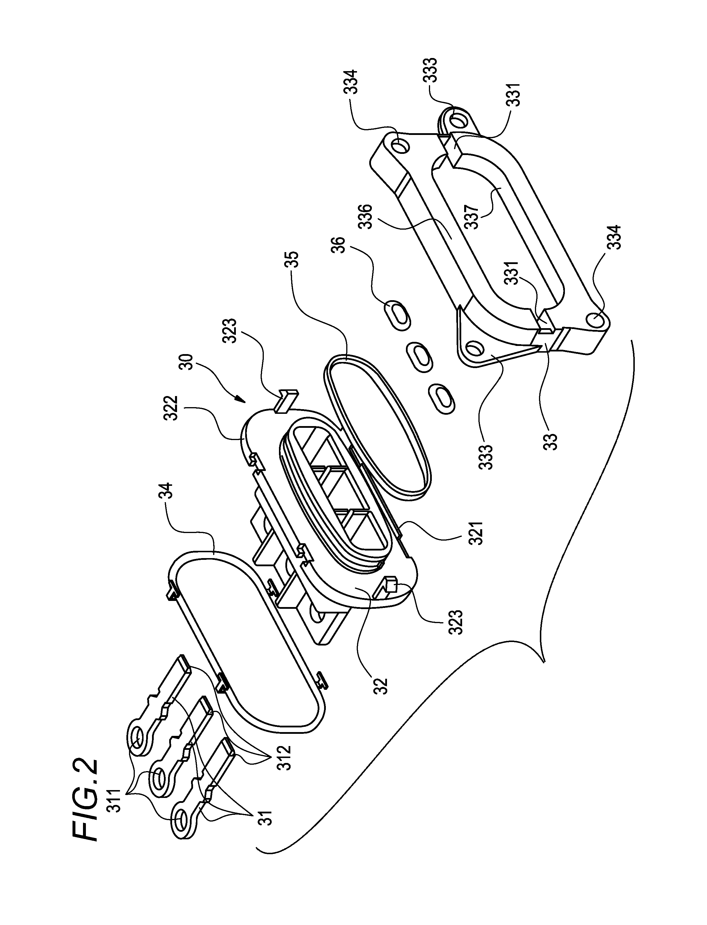
[0082]Furthermore, for the shielded connector 1 of the first embodiment described above, since the thick part 336 equipped at the device-side shield shell 33 also serves as the hood part which accommodates the distal end of the cable-side connector 40, it is not necessary to form a hood part, which accommodates the distal end of the cable-side connector 40, at the device-side resin housing 32, so that the construction of the device-side resin housing 32 can be simplified.

[0083]Furthermore, since the mating shell fixing parts 334 are equipped at the thick part 336, an enough length (depth) is ensured for the screw holes as the mating shell fixing parts 334 and the connecting strength between the device-side connector 30 and the cable-side connector 40 which are screw-connected can be improved.

second embodiment

[0084]FIGS. 4 to 7 show the device-side connector of the shielded connector according to the present invention.

[0085]FIG. 4 is a perspective view of the second embodiment of the device-side connector according to the present invention, FIG. 5 is a perspective view which shows that the device-side connector shown in FIG. 4 is fixed to the shield case, FIG. 6 is a perspective view which shows a section of part of the device-side connector and the shield case shown in FIG. 5, and FIG. 7 is a longitudinal sectional view of the device-side connector and the shield case shown in FIG. 5.

[0086]A device-side connector 30A of the second embodiment is different from the connector 30 of the first embodiment in that a device-side shield shell 33A, into which part of the device-side shield shell 33 is changed, is adopted instead of the device-side shield shell 33 of the first embodiment.

[0087]In the device-side shield shell 33A, the shape of the case-fixing flange parts 333 is changed in response...


PUM


Abstract

A shielded connector includes device-side connector which is fixed to a shield case and a cable-side connector which is attached to an end of an external cable and is fitted to the device-side connector. The device-side connector includes a device-side connection terminal, a device-side resin housing, and a device-side shield shell. The device-side shield shell includes a mating shell fixing part which electrically connects the device-side shield shell and a cable-side shield shell.

Description

CROSS REFERENCE TO RELATED APPLICATIONS[0001]This application is a continuation of PCT application No. PCT / JP2012 / 058012, which was filed on Mar. 27, 2012 based on Japanese Patent Application (No. P2011-079572) filed on Mar. 31, 2011, the contents of which are incorporated herein by reference.BACKGROUND OF THE INVENTION[0002]1. Field of the Invention[0003]The present invention relates to a shielded connector which connects an external cable to a circuit in a shield case of a device.[0004]2. Description of the Related Art[0005]FIG. 8 shows the shielded connector of a prior example. A shielded connector 100 is disclosed in JP-A-2002-373737.[0006]The shielded connector 100 is a connector by which external cables 110 are connected to a circuit in a shield case 103 of a device carried in an automobile or the like.[0007]The shielded connector 100 includes cable-side connection terminals 120 which are crimped and connected to the distal ends of the external cables 110, a resin housing 130 ...

Claims


Application Information

Patent Timeline
Patent Type & Authority Patents(United States)
IPC IPC(8): H01R13/73H01R13/6581H01R13/6591H01R13/74
CPCH01R13/6581H01R13/6591H01R13/748H01R2201/26
Inventor KOBAYASHI, MASAKISUGIYAMA, NORIO
Owner YAZAKI CORP
Learn More