Acoustic wave measuring apparatus, acoustic wave imaging apparatus and method for controlling acoustic wave measuring apparatus
a technology of acoustic wave measurement and imaging apparatus, which is applied in the direction of instruments, specific gravity measurement, applications, etc., can solve the problems of affecting the actual use of the laser, affecting the accuracy of the measurement, and the manufacture of the laser, etc., and achieves the effect of suppressing the cost of the apparatus and sufficient signal strength
- Summary
- Abstract
- Description
- Claims
- Application Information
AI Technical Summary
Benefits of technology
Problems solved by technology
Method used
Image
Examples
first embodiment
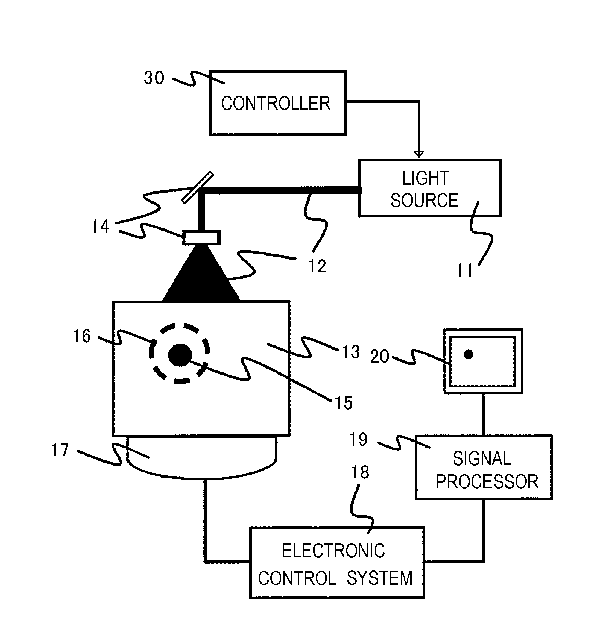
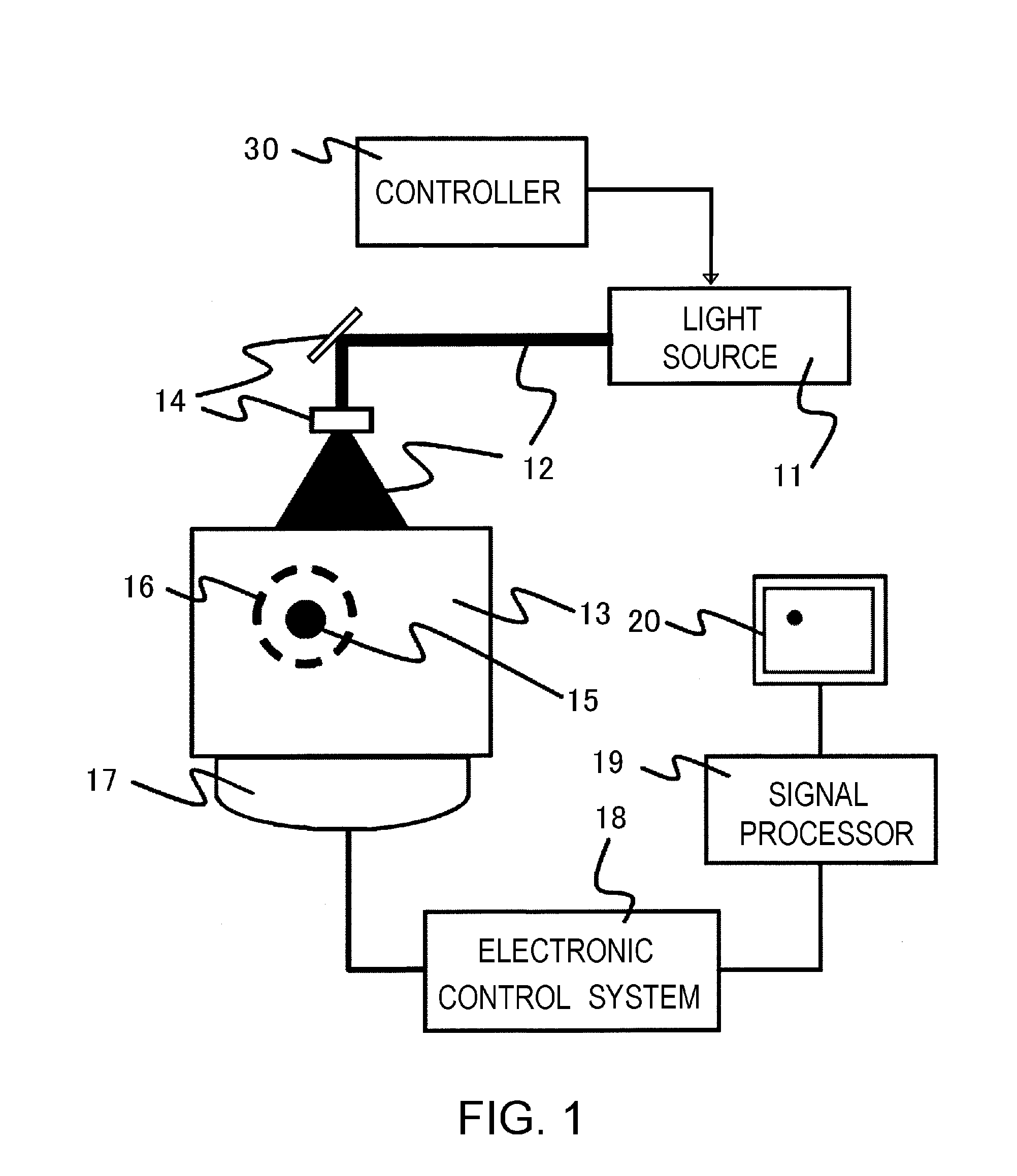
[0071]FIG. 1 shows the configuration of an acoustic wave measuring apparatus according to the present embodiment. This apparatus includes a light source 11, an optical part 14, a detector 17, an electronic control system 18, a signal processor 19, an image display 20, and a controller 30.
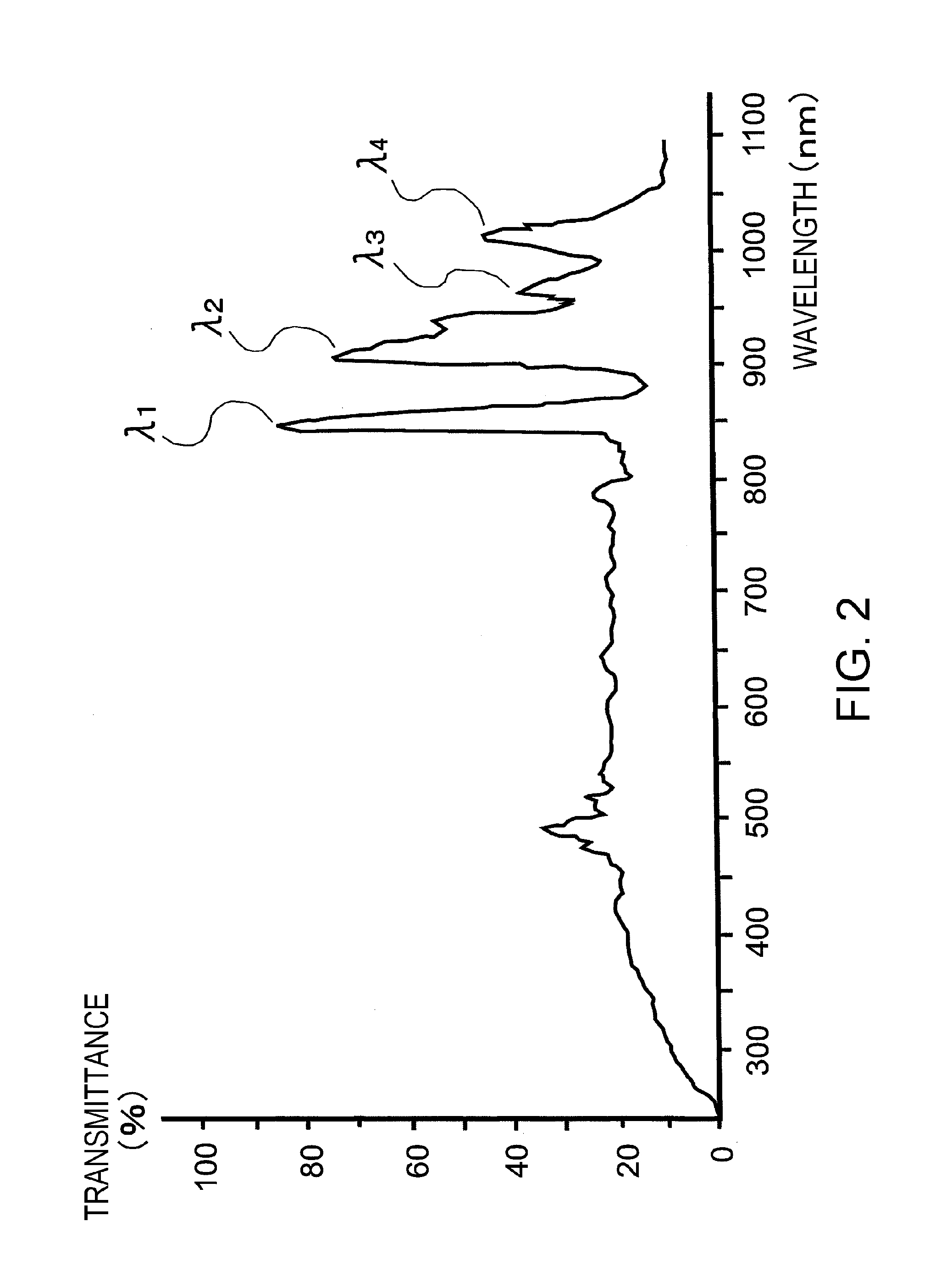
[0072]The light source 11 is an optical system configured of a xenon flash lamp and a plurality of light filters. The xenon flash lamp has the bright-line spectrum in the near-infrared area as shown in FIG. 2. The configuration of the light source and a method for controlling the light wavelength structure using the light filters are described in detail later.
[0073]The light source 11 radiates the light 12 on the subject 13. Though not shown, the light 12 can also be propagated using an optical waveguide such as an optical fiber. When the optical fiber is used, either the light of each light source can be introduced to the surface of the subject by using the optical fiber, or the light from a plural...
second embodiment
[0096]The present embodiment is described with reference to a case in which the micro color filter system is used as a method for controlling the spectrum of the radiated light. FIG. 5 shows the manner in which the micro color filter is configured of a plurality of closely juxtaposing bandpass filters B1 to B4. Reference characters B1 to B4 designate the bandpass filters corresponding to the four wavelength peaks, respectively, of the xenon flash lamp. The bandpass filters B1 to B4 transmit only the light in the wavelength area containing the corresponding peaks, respectively. Also, FIG. 6 shows the manner in which the micro color filter shown in FIG. 5 is used for the optical system. In FIG. 6, the light source is similar to that of the embodiment described above, and the second embodiment is different from the first embodiment in that the former has a light shutter 91 and a micro color filter 92.
[0097]The pixels of the micro color filter 91 are arranged at the same pitch as the pi...
third embodiment
[0101]In the present embodiment, a case is described in which a device of reflection type is used in a method for controlling the spectrum of the radiated light. FIG. 7 shows the configuration of the optical system according to the present embodiment. Alight source portion and a micro color filter 102 have the same configuration as those in the embodiments described above.
[0102]A reflection-type device 101 reflects the light from the light source and guides it to the micro color filter. In the process, reflection or non-reflection of the light can be controlled in accordance with the pixel pitch of the bandpass filter. As a result, the spectrum of the radiated light can be controlled.
[0103]Like in the second embodiment, the liquid crystal panel can be used as the reflection-type device. From the viewpoint of the reflectivity, however, it is not preferable not to use a polarization plate. Instead, a digital mirror device (DMD) is a preferable choice. A multiplicity of micro mirrors i...
PUM
| Property | Measurement | Unit |
|---|---|---|
| wavelength | aaaaa | aaaaa |
| wavelength range | aaaaa | aaaaa |
| wavelength | aaaaa | aaaaa |
Abstract
Description
Claims
Application Information
 - R&D
- Intellectual Property
- Life Sciences
- Materials
- Tech Scout
- Unparalleled Data Quality
- Higher Quality Content
- 60% Fewer Hallucinations
Browse by: Latest US Patents, China's latest patents, Technical Efficacy Thesaurus, Application Domain, Technology Topic, Popular Technical Reports.
© 2025 PatSnap. All rights reserved.Legal|Privacy policy|Modern Slavery Act Transparency Statement|Sitemap|About US| Contact US: help@patsnap.com


