Garment hanging accessory

a technology for accessories and garments, applied in the direction of hose connections, magnetic bodies, machine supports, etc., can solve the problems of skin irritation, potential work, and skin irritation, and achieve the effect of better coordination and choi

Inactive Publication Date: 2015-03-24
LLOYD NICOLE +1
View PDF13 Cites 10 Cited by
  • Summary
  • Abstract
  • Description
  • Claims
  • Application Information

AI Technical Summary

Benefits of technology

[0007]It is an object of the present invention to provide a garment-hanging accessory which enables a user to dispense with the need for use of otherwise conventional garment hanging loops.
[0008]It is another object to provide an accessory of the above type which permits the user thereof to remove conventional garment hanging loop from blouses, tube tops, dresses, skirts, swimwear, lingerie and the like and, in lieu hereof, employ a garment-hanging accessory of the type set forth herein, such that the article of clothing may be readily suspended upon an otherwise conventional shirt or blouse-type of hanger.
[0009]It is a further object of the invention, to provide a garment-hanging accessory which provides a means by which multiple garments may be suspended from a single hanger to provide for better coordination and choice of suitable outfits of interests for men and women.

Problems solved by technology

There is a wide range of articles of clothing which are today provided with such hanging loops since the design of the original garment does not allow the item to hang correctly on a typical hanger whether it is a blouse, tube top, dress or skirt.
Regardless of the manner in which one chooses to suspend or display such garments in one's closet or wardrobe, a remaining and often bothersome issue for many women is that the hanging loops of a given garment, whether it be a blouse, tube top, dress, skirt, lingerie piece or swimsuit, have a potential to work their way outside of the garment where they are typically affixed.
When this occurs, the hanging loop may become visible to the public which, to most women, is unwanted, embarrassing, bothersome, and can be skin irritating depending on the material of the loop.

Method used


Image

  • Garment hanging accessory
  • Garment hanging accessory
  • Garment hanging accessory

Examples


first embodiment

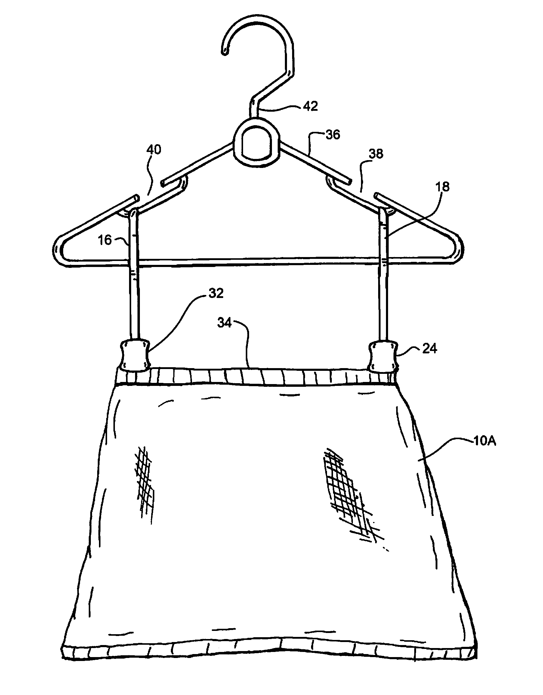
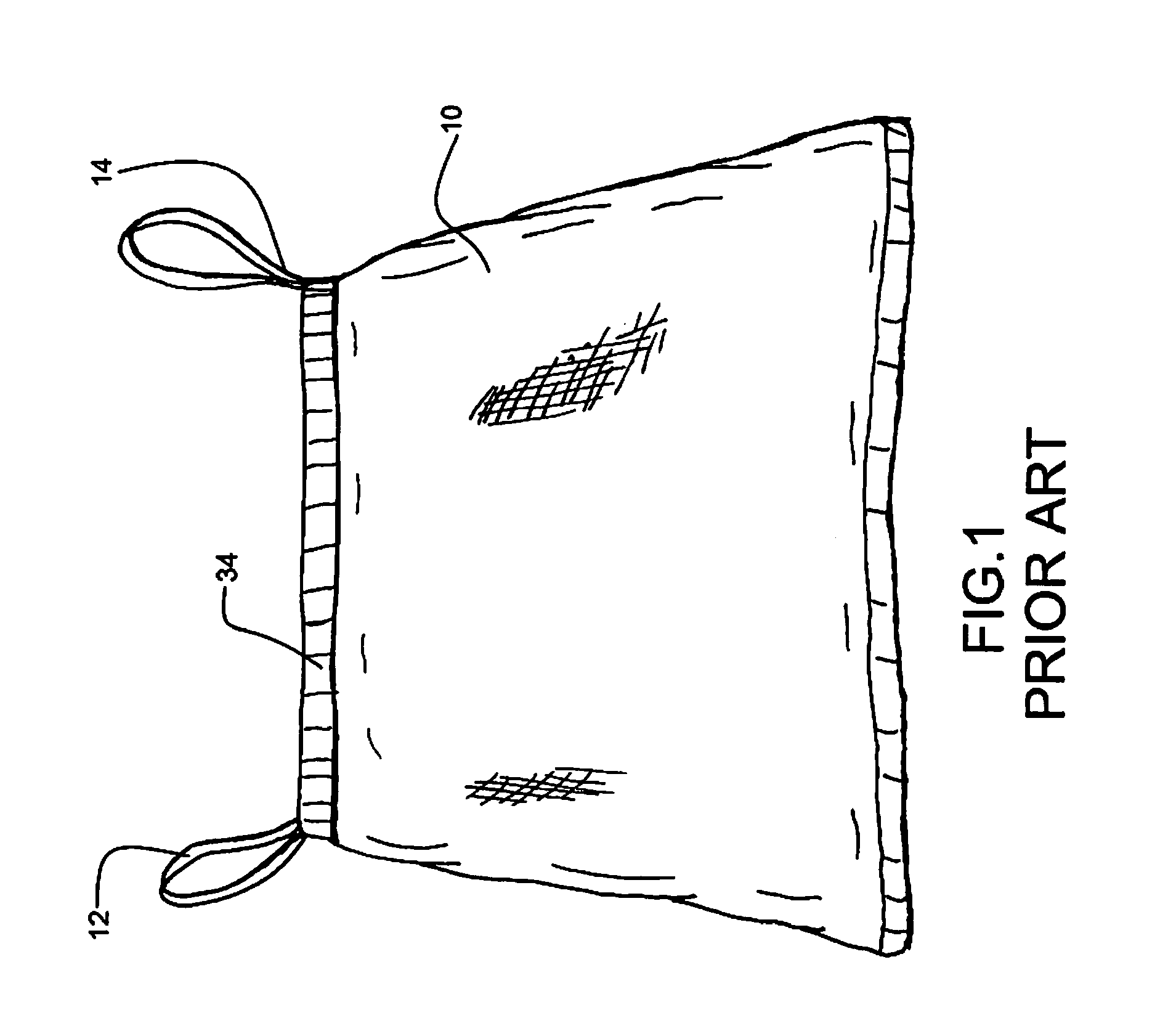
[0023]In the practice of the present invention, such loops 12 are cut from the garment 10 after the purchase thereof and, in lieu of such loops, there is provided a structure 16 of the types shown in FIGS. 2 and 3 in which is shown the present invention. It is noted that the present invention is equally of value in the hanging of garments, such as underwear, not originally provided with any loops.

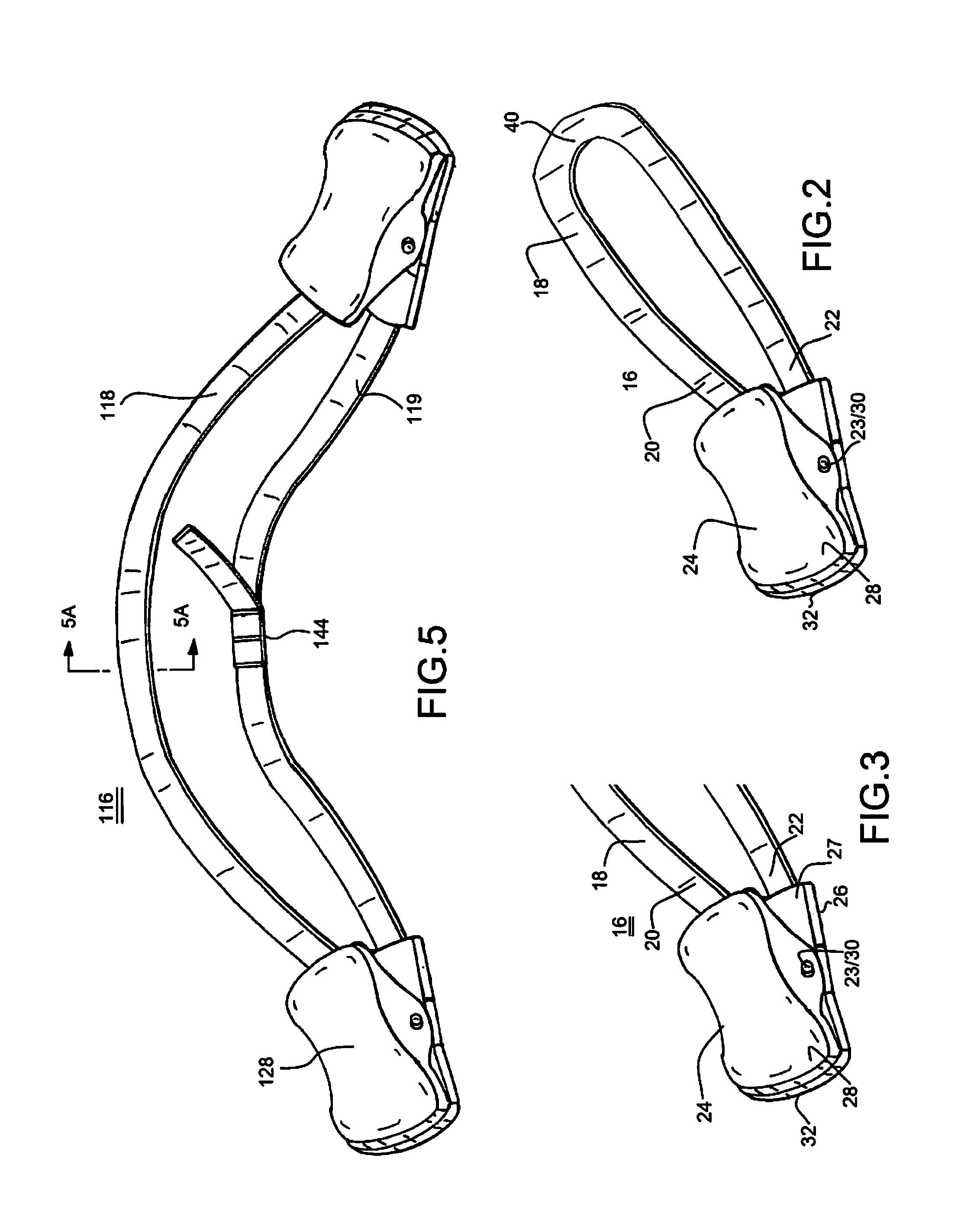
[0024]The inventive garment hanging accessory includes a strip of material 18 having ends 20 and 22 thereof which are secured to respectively opposing surfaces of levers 24 and 26 of a clip 28 which are biased into a normally closed position by a spring 30, an end of which is shown in FIGS. 2 and 3. The preferred manner of connection of ends 20 and 22 to levers 24 and 26 is shown in FIG. 6 and described in connection with the description of FIG. 6 below.

[0025]Spring 30 may for example comprise a coil spring such that engagement ends 32 of clip 28 is normally closed, in the manner shown in F...

embodiment 116

[0027]In FIG. 5 is shown a further embodiment 116 of the present invention in which clips 128 and 129 are provided at each end of a strip 118 and in which a bra length adjuster element 144 is also employed. It is to be understood that adjuster element 144 would typically be used on both sides of strap 118 and, additionally, may be readily employed within strip 18 shown in FIGS. 2 and 3. The benefit of the provision of clips 128 / 129 at each end of strips 118 and 119 is that it enables the hanging of a large number of smaller garments 110 and 111 in the manner shown in FIG. 7.

[0028]Shown in FIG. 5A is a cross-section taken along Line 5A-5A of FIG. 5, indicating that an anti-strip surface 121 may be provided to the underside of strip 118 and to any strip used in the present invention, particularly at the area of contact with a primary hanger 36. See FIG. 4.

embodiment 216

[0029]With reference to the side elevational view of FIG. 6, there is shown a further embodiment 216 of a clip 228 which may be advantageously employed in the practice of the invention. Said clip, like that of earlier embodiments may be provided with padding 246 upon the inner surfaces of forward end 232, or that of the forward ends of any of the above-described embodiments of clip 23 or 123. Further, and particularly to the embodiment of FIG. 6, lever 224 and 226 are shown to include openings 248 within levers 224 and 226 of clip 228 such that strap 218 may pass through opening 248, this as opposed to the securement of end 27 (see FIG. 3) of strip 18 to each inner surface of levers 24 and 26 of clip 28. Where this embodiment is employed, a loop may be formed of strip 218 after ends thereof have passed through opening 248 of levers 224 and 226. Alternatively, opposite ends of strips 218 and 219 may then be fastened together to form the embodiment shown in FIG. 2 or provided with a c...


PUM


Abstract

A garment-hanging accessory includes a strip of material having a first end and a second end; and a clip having an engaging end biased into a normally closed position and openable upon application of pressure upon opposing levers at an opposite end of the clip, the levers connected by a spring secured about a fulcrum point between the levers, each end of the strip of material secured to a respective opposite side of each of the opposing levers, opposite ends of each lever, not secured to either of the ends of the strip of material, co-acting to define a garment engaging end when the clip is in its normally closed position. The unsecured portion of the strip opposite the clip is suspended upon a primary garment hanger.

Description

AREA OF INVENTION[0001]The present invention relates to garment hanging accessories and, more particularly, to a garment hanging system adapted to hang upon a primary clothing hanger.BACKGROUND OF THE INVENTION[0002]As is well-known to women who wear various types of blouses, tube tops dresses, skirts, undergarments and swimwear, such garments often are provided with so-called hanging loops, the purpose of which is to facilitate the hanging of such garments in one's wardrobe in a manner which is more visible, less wrinkled and therefore functional than simply folding the same and keeping them in a credenza or chest of drawers. There is a wide range of articles of clothing which are today provided with such hanging loops since the design of the original garment does not allow the item to hang correctly on a typical hanger whether it is a blouse, tube top, dress or skirt. Because of the range of articles of clothing which are today provided with such hanging loops, one must either pur...

Claims


Application Information

Patent Timeline
Patent Type & Authority Patents(United States)
IPC IPC(8): A47G25/48F16B2/20A44B11/06F16B2/10
CPCA47G25/486A47G25/48A47G25/483F16B2/20F16B2/10D06F55/02H01F7/0252Y10T24/32Y10T24/3428Y10T24/3437Y10T24/3433Y10T24/1397Y10T24/318Y10T24/4745
Inventor LLOYD, NICOLELLOYD, KIM
Owner LLOYD NICOLE
Why Eureka
Try Eureka