
Conveyor belt with composite link

a conveyor belt and composite technology, applied in the direction of conveyors, transportation and packaging, etc., can solve the problems of plastic belts typically failing, metal belts failing, and wear at the surface of links, so as to reduce wear and reduce wear on surfaces, prevent fatigue

Active Publication Date: 2015-03-24
ASHWORTH BROS
View PDF32 Cites 10 Cited by
  • Summary
  • Abstract
  • Description
  • Claims
  • Application Information

AI Technical Summary

Benefits of technology

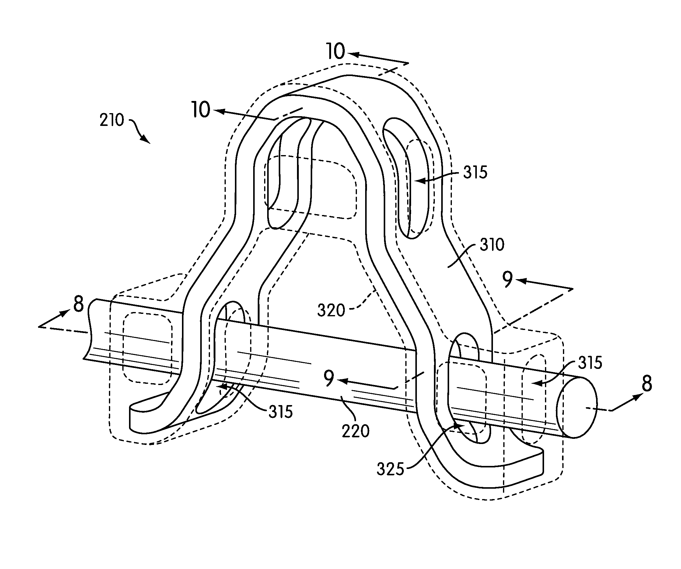
[0009]A conveyor belt edge link formed of a material to provide strength and prevent fatigue and a material to reduce wear, and a conveyor belt that incorporates such edge and other similar links, is described. In some embodiments, the link is a composite link formed of a metal connecting structure that provides strength to the link and a bearing structure that reduces wear on surfaces of the link by inhibiting metal-to-metal contact. This allows the link to have the advantages of both metal links, which are strong and less prone to fatigue than plastics, and plastic links, which are not as prone to wear as metal links.

Problems solved by technology

Metal conveyor belt links typically have excellent strength properties, but exhibit wear at surfaces where the links contact the rods.
On the other hand, plastic conveyor belt links are typically resistant to wear at contact surfaces, but are sometimes less strong than metal belts commonly resulting in failure due to fatigue and / or excess loading.
That is, metal belts commonly last as long as a plastic belt configured for similar duty, however, the plastic belt will typically fail due to fatigue or an instantaneous load spike, whereas the metal belt will fail due to wear.
In addition, different portions of a turn curve conveyor belt are loaded differently, such that a material that may be well-suited for a given portion of a conveyor belt may be less well-suited for other portions of the conveyor belt.
These and other problems exist with respect to conveyor belts and / or conveyor belt links.

Method used


Image

  • Conveyor belt with composite link
  • Conveyor belt with composite link
  • Conveyor belt with composite link

Examples


Embodiment Construction

[0043]The present disclosure describes systems and methods for providing modular conveyor belt links with both wear resistance and strength.

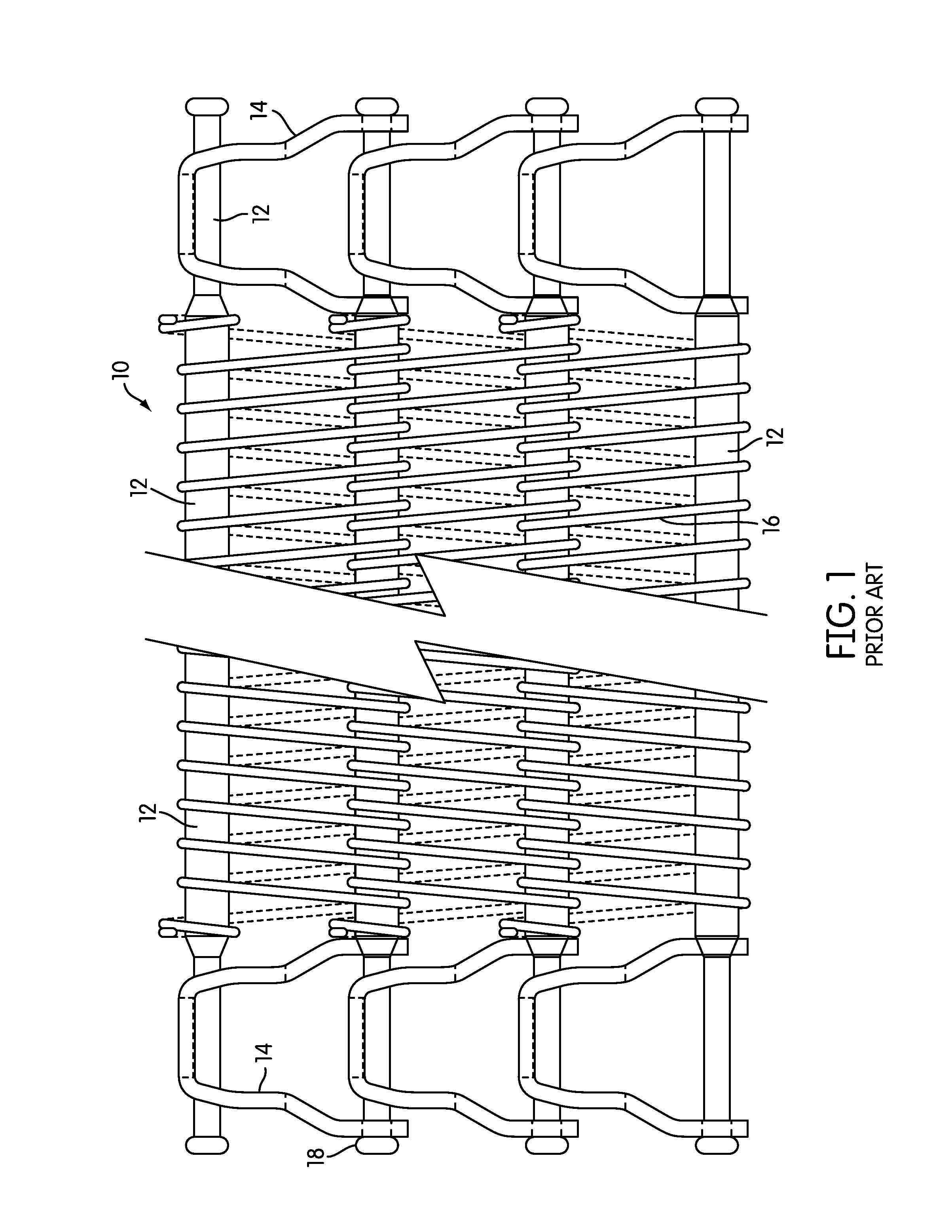
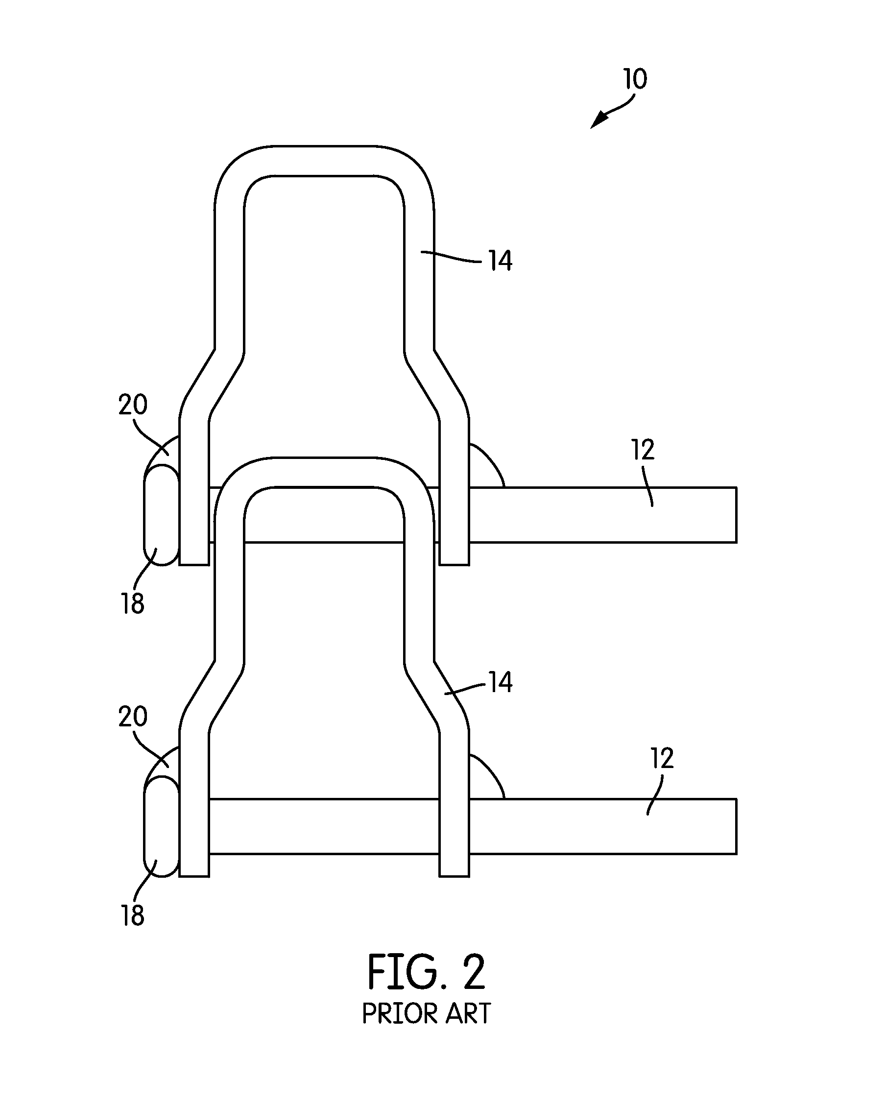
[0044]Examples of basic conveyor belt structures and manufacturing methods can be found in U.S. Pat. No. 5,954,188, which is incorporated herein by reference. The accompanying FIG. 1 corresponds to FIG. 1 of the '188 patent, and illustrates a typical prior art modular conveyor belt 10. Conveyor belt 10 includes rods 12 connected by links 14 and covered by a mesh 16 to provide additional support for the goods transported on conveyor belt 10.

[0045]In some cases, a buttonhead 18 may be formed on the ends of rods 12 to act as a stop for links 14. A weld is also typically formed between buttonhead 18 and link 14 for a stronger and more secure connection between rods 12 and links 14. In other cases, a buttonless configuration may be employed, wherein the rod is welded to the link without creating a significant protrusion beyond the leg of the link.

[00...


PUM


Abstract

A link for a modular conveyor belt may include a supporting structure and a bearing structure covering at least a portion of the supporting structure. The supporting structure may have a tensile strength that is higher than the bearing structure, and the bearing structure may be more resistant to wear than the supporting structure.

Description

BACKGROUND[0001]1. Field of the Invention[0002]The present disclosure relates generally to components for modular conveyor belts. More particularly, the present disclosure relates to composite links for modular conveyor belts.[0003]2. Description of Related Art[0004]Conveyor belts are popularly used in a number of different industrial fields to provide continuous motion of goods during manufacture, shipping, and other processes. Industrial conveyor belts generally include a series of spaced apart rods connected via a series of links, which are welded or otherwise coupled to the rods. Such belts are commonly referred to as modular conveyor belts.[0005]For the manufacture of small items, the rods may be covered with a fabric, plastic, or metal overlay, such as a mesh, to prevent the small items from slipping between the rods and falling to the manufacturing floor. Further, the structure of the links that make up modular conveyor belts varies.[0006]Generally, conveyor belts and links a...

Claims


Application Information

Patent Timeline
Patent Type & Authority Patents(United States)
IPC IPC(8): B65G17/08B65G17/06
CPCB65G17/063B65G17/083B65G17/086B65G15/54B65G2812/02128
Inventor NEELY, DARROLL JOSEPH
Owner ASHWORTH BROS
Learn More