Bridging terminal

a bridging terminal and terminal technology, applied in the direction of coupling contact members, coupling device connections, printed circuits, etc., can solve the problems of poor bonding strength, poor electrical conductivity, and compromise of the stability of the bridging terminal, so as to improve the contacting area and contacting points, improve the bonding strength and stability, and prevent elastic fatigue and premature failure. the effect of premature failur

Active Publication Date: 2015-03-17
DINKLE ENTERPRISE CO LTD
View PDF7 Cites 3 Cited by
  • Summary
  • Abstract
  • Description
  • Claims
  • Application Information

AI Technical Summary

Benefits of technology

[0011]With the foregoing configuration, the disclosed bridging terminal can increase contacting area and contacting points, so as to improve electric conductivity, bonding strength and stability, while preventing elastic fatigue and premature failure.
[0012]The cap may have two opposite recessed portions for users' easy holding. With the recessed portions, users can easily exert force on the cap, so as to hold and remove the bridging terminal.

Problems solved by technology

When bridging two terminals, the bridging terminal provides a modest contacting area with the two terminals, resulting in unsatisfactory electric conductivity and poor bonding strength, which means that the bridging terminal and the two terminals are likely to come off from each other, and that the stability of the bridging terminal is compromised.
However, in the case where the users' force is large to the extent that the bridging terminal has elastic fatigue (fatigue deformation), the bridging terminal will become unusable.

Method used


Image

  • Bridging terminal
  • Bridging terminal
  • Bridging terminal

Examples


Embodiment Construction

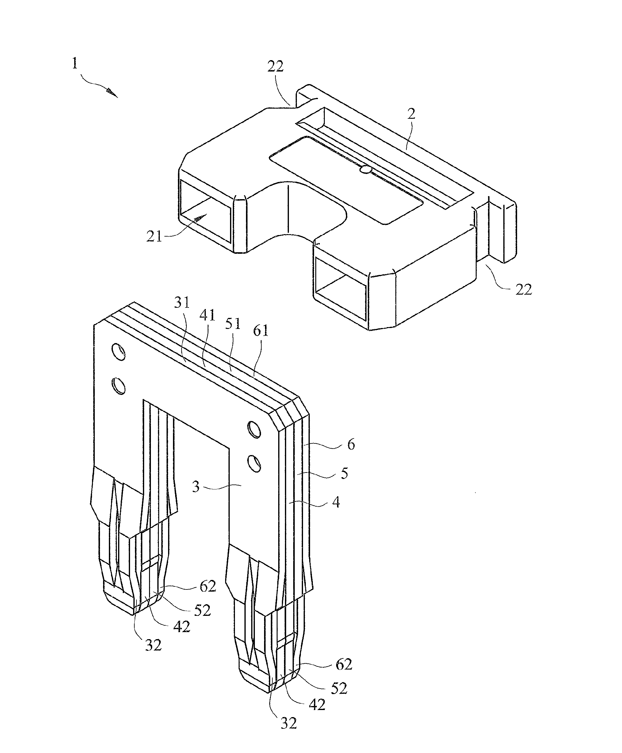
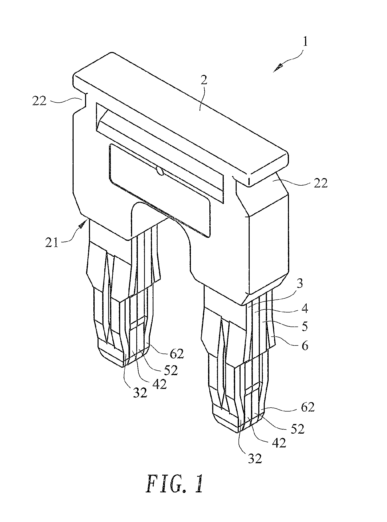
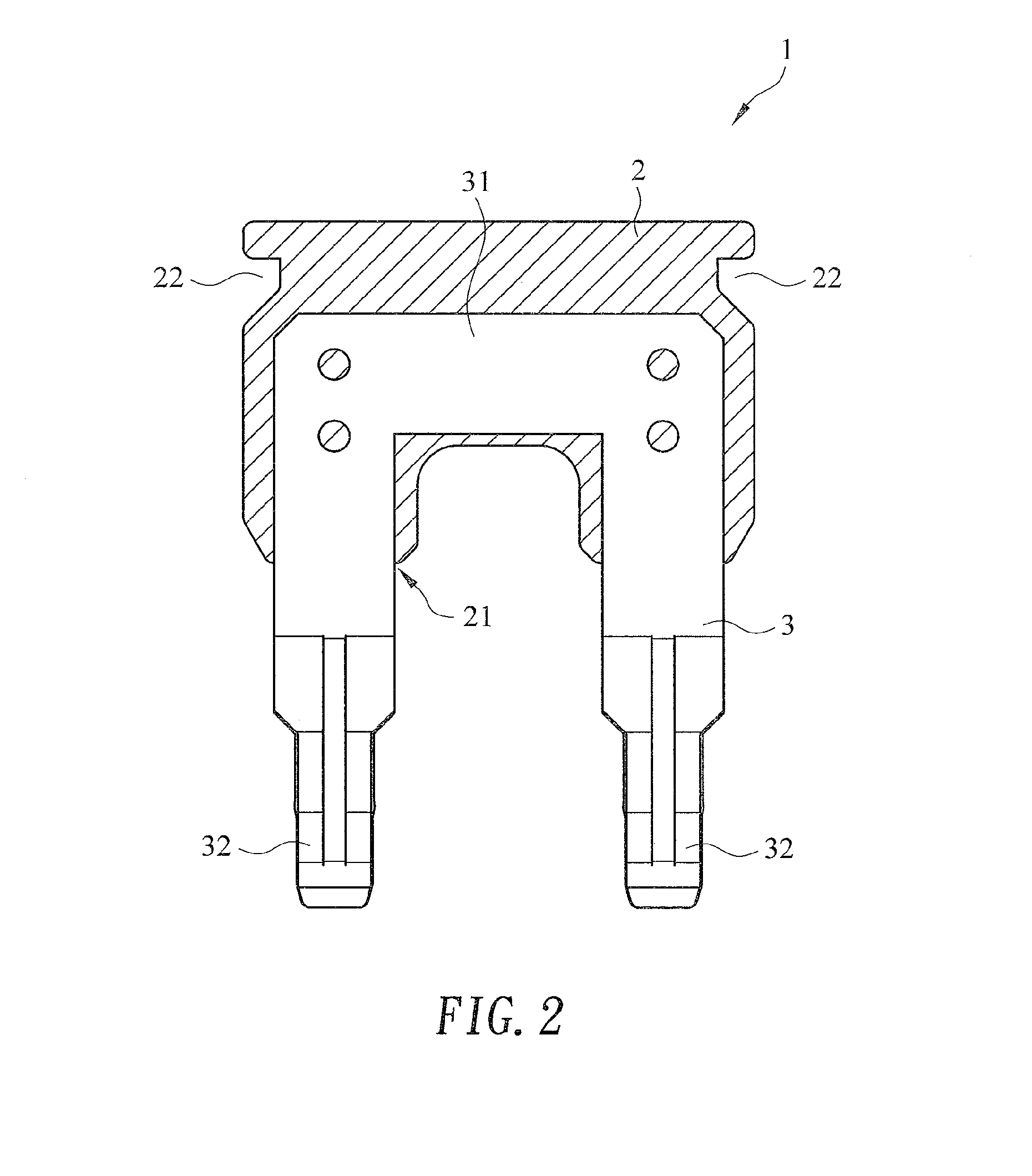
[0021]Refer now to FIG. 1 and FIG. 2, which are a perspective view and a cross-sectional view of a first preferred embodiment of the present invention, respectively.

[0022]As shown, the disclosed bridging terminal 1 comprises a cap 2, a first flexible conductive piece 3, a second flexible conductive piece 4, a third flexible conductive piece 5 and a fourth flexible conductive piece 6.

[0023]Now refer to FIG. 3, which is an exploded view of the first preferred embodiment of the present invention, showing the cap and the flexible conductive pieces, and also refer to FIG. 1 and FIG. 2.

[0024]As shown in FIG. 3, the cap 2 comprises an assembling chamber 21, such that the first flexible conductive piece 3, the second flexible conductive piece 4, the third flexible conductive piece 5 and the fourth flexible conductive piece 6 when piled together can be received in the assembling chamber 21 of the cap 2, as shown in FIG. 1 and FIG. 2. The details of the components will be given below.

[0025]No...


PUM


Abstract

A bridging terminal includes a cap and four conductive pieces. Each of the flexible conductive pieces has two pin portions and a connecting portion. The connecting portions are combined in an assembling chamber of the cap. The pin portion of the first flexible conductive piece has a front-left-outer facet and a front-right-outer facet jutting frontward, and has a flexible arch jutting backward. The second and third flexible conductive pieces have each of their pin portions including a left-outer facet, a right-outer facet and a slot. The pin portion of the fourth flexible conductive piece has a rear-left-outer facet and a rear-right-outer facet jutting backward, and has a flexible arch jutting frontward. When the flexible conductive pieces are aligned and piled, the flexible arches are received in the corresponding slots. Thereby, the bridging terminal provides improved electric conductivity, bonding strength and stability, while preventing elastic fatigue and premature failure.

Description

BACKGROUND OF THE INVENTION[0001]1. Technical Field[0002]The present invention relates to bridging terminals, and more particularly, to a bridging terminal helpful to increase the contacting area and contacting points, so as to improve electric conductivity, bonding strength and stability, while preventing elastic fatigue and premature failure.[0003]2. Description of Related Art[0004]It can be easily seen in an average electronic appliance that multiple transmission lines are used for signal transmission. For connecting electronic devices, transmission lines are collected at a terminal and such terminals of individual electronic devices are connected with each other, such that signals can be transmitted among these electronic devices.[0005]Moreover, in the level of electronic devices, if it is appropriate, a bridging terminal may be provided for connecting (bridging) two terminals in order to, for example, create a short circuit between the two terminals.[0006]An existing bridging t...

Claims


Application Information

Patent Timeline
Patent Type & Authority Patents(United States)
IPC IPC(8): H01R31/08H01R9/24
CPCH01R9/2491H01R13/05H01R31/08
Inventor WU, SHANG TSAI
Owner DINKLE ENTERPRISE CO LTD
Why Eureka
Try Eureka